Mid Size & Full Size RTs
Engine Powered
Page 13
Section 2 - Familiarization Control Functions
It is the responsibility of the operator to read, completely understand and follow all instructions and warnings
contained in this operating manual and on the aerial platform.
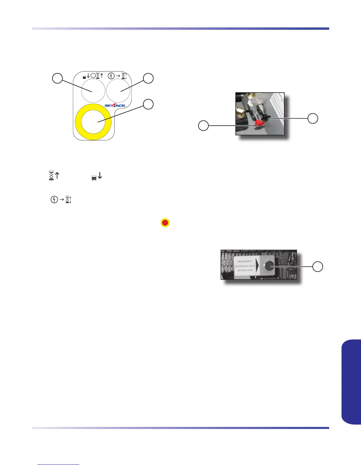
2.2-5 Base Control Console
This control console is located at the rear of the
hydraulic/electrical compartment. It contains the
following controls:
21
3
Figure 2-2. Base Control Console
1. Lower/Neutral/Raise Switch - This switch controls
“ ” raising or “ ” lowering of platform.
2. Enable Switch - When selected and held, this
“
” switch allows the lift and auxiliary start
functions to operate.
3. Emergency Stop Button - This button “ ”,
when depressed, disconnects power to the control
circuit.
2.2-6 Brake System
The brake system is located on the main manifold in
the hydraulic/electrical compartment. The brake must
be manually disengaged before pushing, winching or
towing. Refer to Section 2.5 for procedure on how to
release the brake manually. The system contains the
following controls:
2
1
Disc Brake
Figure 2-3. Brake System
1. Brake Hand Pump
2. Brake Auto Reset Valve Plunger
2.2-7 Emergency Powered Extension Platform
Retraction System (Models 92xx)
This system is located in the hydraulic/electrical
compartment. In the event of an emergency or an engine
malfunction, this switch (item 1) can retract the powered
extension platform from the base. Refer to Section 3.8-9
for emergency retraction procedure.
1
Figure 2-4. Emergency Powered Extension Platform
Retraction System
FAMILIARIZATIONFAMILIARIZATION