Mid Size & Full Size RTs
Engine Powered
Page 15
Section 2 - Familiarization Control Functions
It is the responsibility of the operator to read, completely understand and follow all instructions and warnings
contained in this operating manual and on the aerial platform.
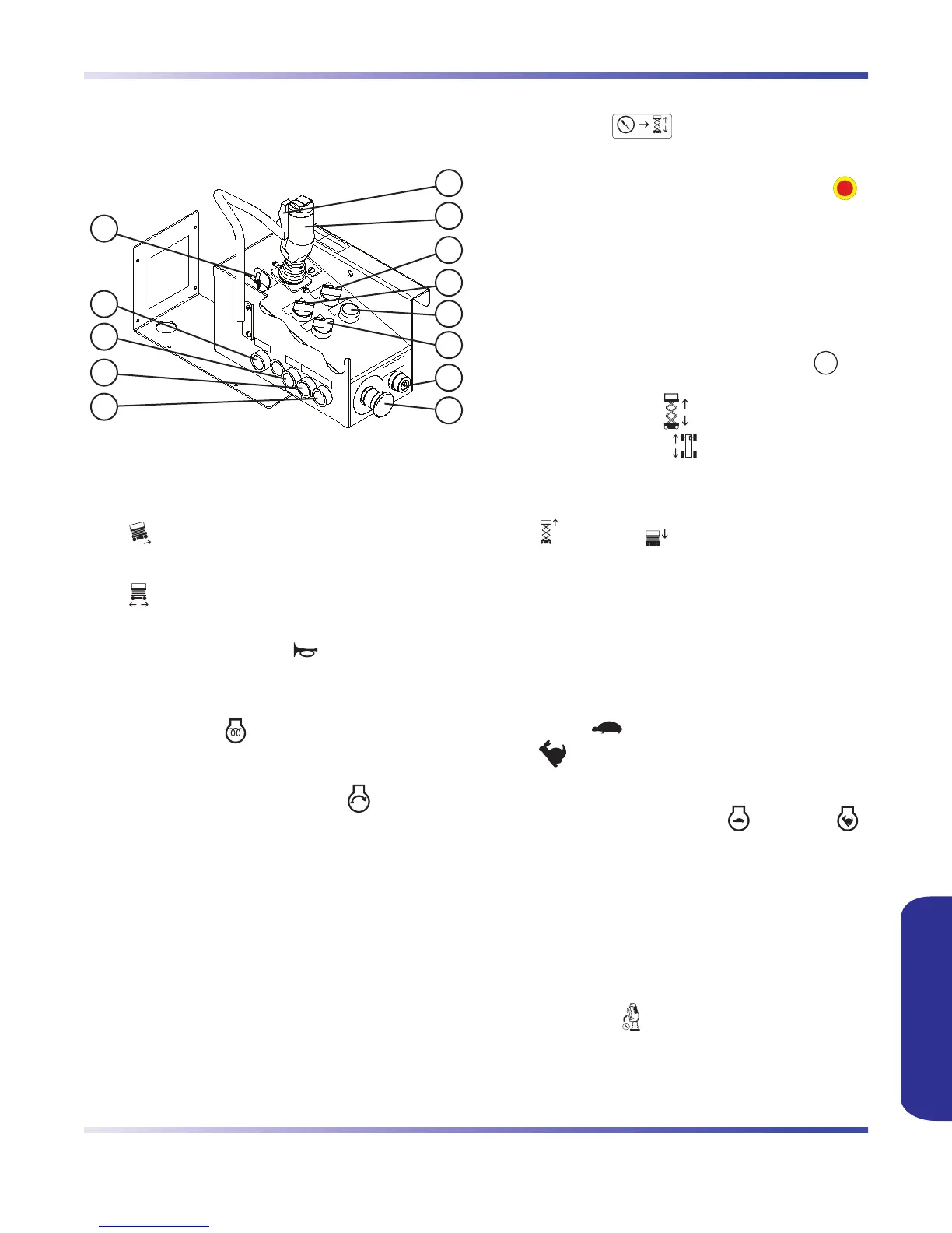
2.2-10 Platform Control Console
This removable control console is mounted at the right
front of the platform. It contains the following controls:
2
1
3
4
5
6
7
8
10
9
11
12
13
Figure 2-8. Platform Control Console
1. Torque Switch - This switch, when in
“
” high torque position, cuts out high range
and 3rd speed to provide maximum torque when
climbing grades and on rough terrain. When in
“
” low torque position, all three speeds are
available.
2. Horn Pushbutton - This “ ” pushbutton sounds
an automotive-type horn.
3. Glow Plug Pushbutton (Diesel) - This pushbutton
energizes the “
” glow plugs to aid in starting a
cold diesel engine.
4. Engine Start Pushbutton - This “ ” pushbutton
energizes the engine starter motor.
NOTE
The engine start pushbutton is interlocked
with the oil pressure switch. If engine stalls
or does not start immediately, this button
will not work for a few seconds while oil
pressure bleeds off.
5. Lift Enable Pushbutton - When depressed and
held, this “
” pushbutton allows the lift
functions to operate.
6.
Emergency Stop Button - This button “ ”,
when depressed, disconnects power to control
circuit and shuts engine off. The red colored light
indicates upper control availability and overload
status. When the light is continuously illuminated,
upper controls are available. When the light is
flashing, it signals an overload function. Refer to
Section 2.2-4.
7.
Off/Lift/Drive Key Switch - Selecting “ ” off
position disconnects power from both lift and drive
circuits. Selecting “
” lift position energizes the
lift circuit. Selecting “ ” drive position energizes
the drive circuit.
8. Raise/Off/Lower Switch - This switch controls
“
” raising or “ ” lowering of the platform.
9. Operation Light - The red colored light indicates
upper control availability and overload status.
When the light is continuously illuminated,
upper controls are available. When the light is
flashing, it signals an overload function. Refer to
Section 2.2-4.
10. Low/High Speed Range Switch - This switch
selects “
” low speed range (high torque) or
“
” high speed range (low torque).
11. Low/High Throttle Switch - This rotary switch
allows selection between “
” low and “ ”
high engine throttle speeds.
12. Drive/Steer Controller - This one-hand lever
controls drive speed and steer motion. Internal
springs return it to neutral when controller is
released. The rocker switch on top of controller
handle controls steering function.
13. Drive/Steer Enable Trigger Switch - This
momentary “ ” switch energizes the controller.
It must be held depressed continuously while
engaging either drive or steer functions.
FAMILIARIZATIONFAMILIARIZATION