Skytech 3001
REV 12/01
Page 5 of 8
When the ambient temperature at the THERMISTOR, inside the receiver case, reaches 130
0
F
, the THERMISTOR will automatically shut the
appliance down and the RECEIVER will begin emitting a series of 2 “beeps”, every 4 seconds. When the ambient temperature, at the
RECEIVER, drops between 120
0
F
and 130
0
F
, the user can reactivate the appliance by pushing the MODE button on the transmitter. The
word ON must display on the LCD screen. When the MODE button is pressed to ON, the THERMISTOR “resets” itself and the fireplace will
begin operating again. However, the “beeping” will continue, if the ambient temperature remains between 120
0
F
and 130
0
F
. This “beeping”
alerts the user that the RECEIVER should be repositioned so the ambient temperature drops below 120
0
F
.
When the temperature drops below 120
0
F
, the “beeping” will cease, providing the user has “reset” the THERMISTOR by pushing the
MODE button to ON to operate the appliance, either manually or thermally. Allow sufficient time for the receiver to cool below 120
0
F
,
and then press MODE button to stop beeping.
INSTALLATION INSTRUCTIONS
WARNING
This remote control system must be installed exactly as outlined in these instructions. Read all instructions completely before
attempting installation. Follow instructions carefully during installation. Any modifications of the SKYTECH remote control or any of its
components will void the warranty and may be pose a fire hazard.
Do not connect any gas valve or electronic module directly to 110-120VAC power. Consult gas appliance manufacturer’s instructions
and wiring schematics for proper placement of all wires. All electronic modules are to be wired to manufacturer’s specifications.
The following wiring diagrams are for illustration purpose only. Follow instructions from manufacturer of gas valve and/or electronic
module for correct wiring procedures. Improper installation of electric components can cause damage to electronic module, gas valve
and remote receiver.
INSTALLATION
The remote receiver can be either wall-mounted in a standard plastic switch box or placed on or near the fireplace hearth. Preferably, the
remote receiver should be wall-mounted in a plastic switch box, as this will protect its electronic components from both the heat produced by
the gas appliance and potential damage or abuse that can occur if it is left exposed on the hearth. PROTECTION FROM EXTREME HEAT IS
VERY IMPORTANT. Like any piece of electronic equipment, the remote receiver should be kept away from temperatures exceeding 130
0
F
inside the receiver case. Battery life is also significantly shortened if batteries are exposed to high temperatures.
Make sure the remote receiver switch is in the OFF position. It is recommended that 18 gauge stranded or solid wires (included) be used to
make connections between the terminal wiring block on the millivolt gas valve or electronic module and the wire terminals on the remote
receiver. For the best results, use 18 gauge stranded or solid wire, with no splices and measuring no longer than 20 ft.
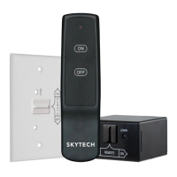
WALL MOUNTING
Install 4 AA-size 1.5 ALKALINE batteries in the remote receiver. For best performance, remote receiver batteries should be factory fresh when
installed. Very little battery power is required to operate the remote receiver, but the electronics are tuned to operate best when battery output
is greater than 5.3 volts. Four new AA batteries should provide an output voltage of 6.0 to 6.2 volts.
Be sure batteries are installed with the
(+) and (-) ends facing the correct direction
.
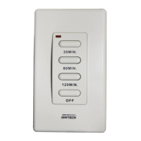
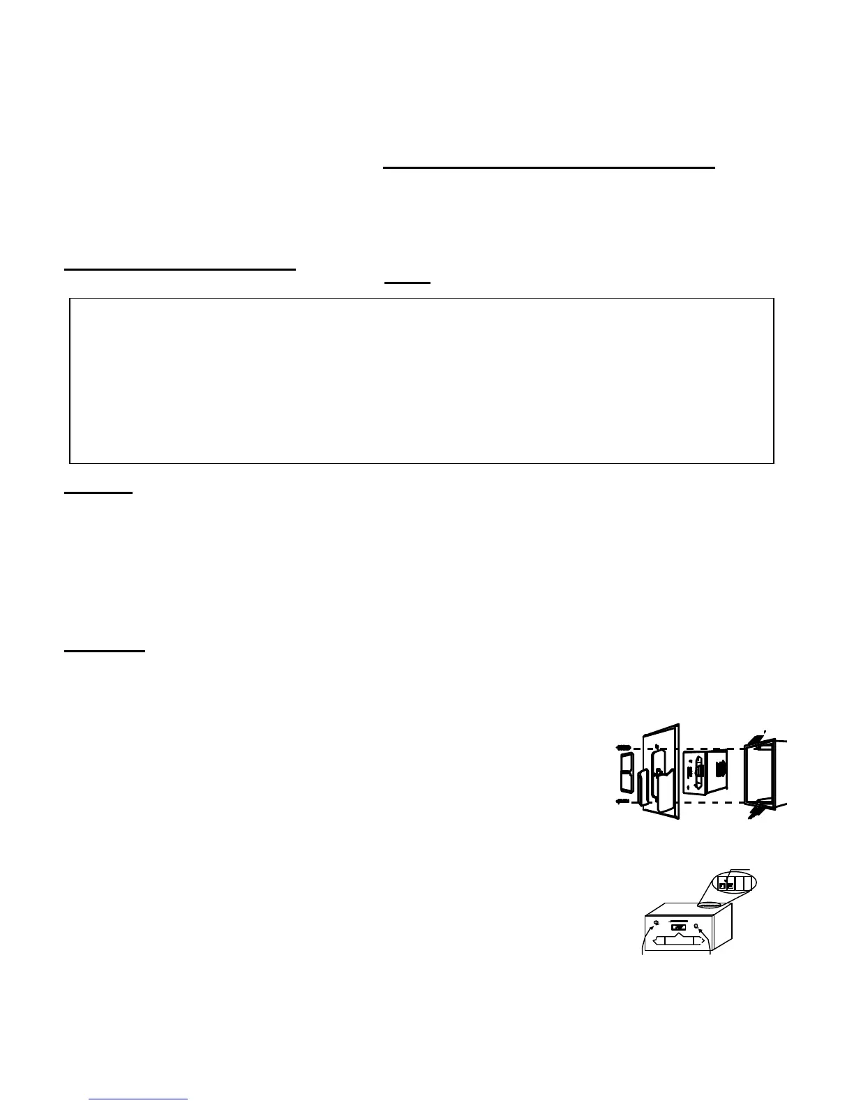
To attach wall mount cover Plate/Transmitter holder to Receiver box:
Position the receiver as shown in diagram to the left with lower tab on
wall mount cover plate into groove of receiver (Make sure ADJ hole
and LEARN hole on cover plate properly aligns with remote receiver)
Pull receiver up and snap into top tab of cover plate.
Position the wall mount cover plate so the word ON is facing up; then,
install the remote receiver into the plastic switch box using the two long
screws provided. Push the slide Button over the receiver slide switch only
after making sure the remote receiver has LEARNED the transmitter’s
security code (see MATCHING SECURITY CODES). NOTE: slide
Button covers both ADJ and Learn holes when properly installed.
NOTE: The remote receiver will only respond to the transmitter when the 3-position slide button
on the remote receiver is in the REMOTE position. If the system does not respond to the battery
transmitter on initial use, see MATCHING SECURITY CODES, and recheck battery positions in
the remote receiver.
 Loading...