TR Series
5
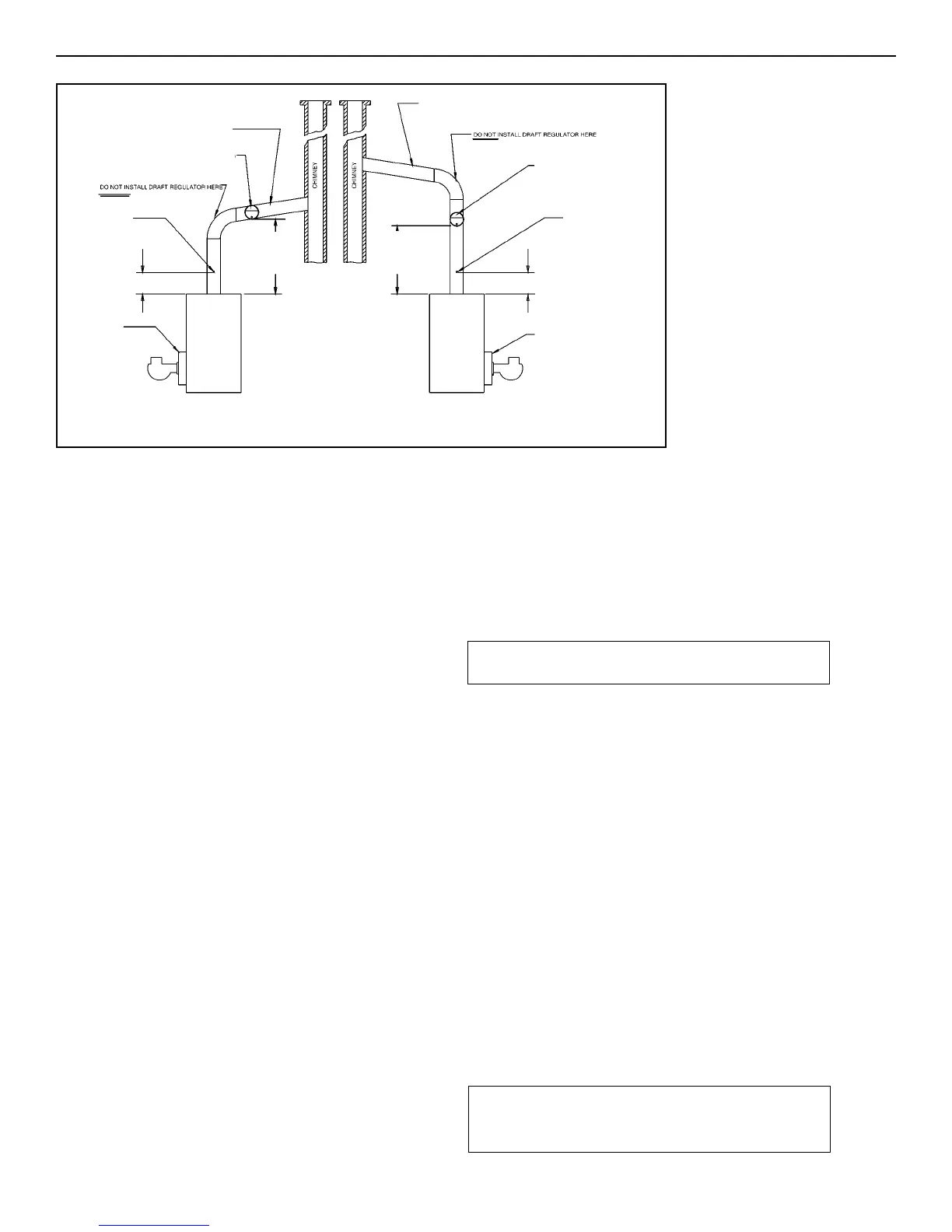
Figure 3.
Barometric Draft
Regulator
Location
PITCH UP
21 mm/m (1/4" per linear foot)
Drill 6 mm (1/4")
HOLE TO
MEASURE
DRAFT, SMOKE,
CO
2
and stack
temperature
PITCH UP
21 mm/m (1/4" per linear foot)
457 mm
(18")
MINIMUM
229 mm (9")
DRILL 6 MM (1/4")
HOLE TO
MEASURE DRAFT,
SMOKE, CO
2
AND
STACK
TEMPERATURE
MAINTAIN 0.5
MM (0.02")
W.C. DRAFT
(OVER-FIRE)
MAINTAIN 0.5
MM (0.02")
W.C. DRAFT
(OVER-FIRE)
BAROMETRIC DRAFT REGULATOR
INSTALLED ON HORIZONTAL CONNECTION
BAROMETRIC DRAFT REGULATOR
INSTALLED ON VERTICAL RISE
229 mm (9")
457 mm
(18")
MINIMUM
CHIMNEY REQUIREMENTS
A. The chimney must be constructed in accordance with all
local applicable codes and the National Board of Fire
Underwriters. See boiler models and rating table shown on
page 2 for chimney sizes.
B. Check chimney condition.
Existing chimneys and stacks may have deteriorated; without
repairs their use would be hazardous. Before connecting to an
old chimney or stack:
1. Clean it.
2. Inspect it thoroughly.
3. Remove obstructions.
4. Replace worn sections of metal stacks.
5. Seal bad masonry joints.
6. Repair damaged linings.
C. Where more than one appliance vents into a common chimney,
the area of the common Breaching should at least equal the
area of the largest appliance flue plus 50% of the additional flue
areas.
D. Breaching area must not be reduced at connection into chim
ney. Breaching must be inserted into, but not beyond, inside of
chimney liner.
E. Chimney height shall extend at least 1 m (3 feet) above where it
passes through the roof of the building, and at least 0.5 m (2
feet) above any ridge within 3 m (10 feet) of the chimney.
F. The use of a vent cap, where permitted by code, gives addition
al protection against adverse wind conditions and precipitation.
G. Flue Connection: Connect flue pipe between top of boiler and
chimney. Horizontal sections of flue pipe must be pitched
upward to the chimney at least 21 mm/m (
1
/4" per foot). Flue
must be inserted into, but not extend beyond, the inside wall of
the chimney flue. Install draft regulator in flue pipe, as shown in
figure 3.
BLOCKED VENT SAFETY SWITCH
All Intrepid TR Series boilers must be installed with a Blocked
Vent Safety Switch. The Blocked Vent Safety Switch will
detect spillage of flue gases due to a blocked vent or
inadequate draft.
The Blocked Vent Safety Switch supplied with all Intrepid TR
Series boilers must be installed on the barometric damper.
Refer to the manufacturers instructions provided with the
Blocked Vent Safety Switch for installation, location
instructions.
The Blocked Vent Safety Switch is to be FIELD wired, see
wiring diagrams, into the line voltage connection being wired
into the junction box, so the Blocked Vent Safety Switch
breaks power supply to the boiler shutting it down in the
event of a spillage.
IMPORTANT: The Blocked Vent Safety Switch must be wired
in accordance with The National Electrical Code, the
Installation of Oil Burning Equipment, CSA B139. The
installation must also conform to any applicable local codes,
the manufacturer's instructions, the requirements of this
Slant/Fin manual, and any authority having jurisdiction.
Where there is any difference the more stringent requirement
shall govern.
Check the operation of the Blocked Vent Safety Switch:
A: Block chimney or vent pipe.
B: Adjust thermostat to call for heat.
C: Allow approximately two minutes for the system to back up
and the burner to shut down.
D: Perform steps B and C again.
AIR SUPPLY AND VENTILATION
(see CSA B139, latest edition, Section 7)
Sufficient air for combustion and ventilation in the boiler room
must be provided. Failure to do this will result in poor combus
tion, heavy sooting and health hazards.
BAROMETRIC DRAFT
REGULATOR
BAROMETRIC DRAFT
REGULATOR
CAUTION: DISCONNECT ELECTRICAL POWER WHEN
WIRING.
CAUTION: AN OIL-FIRED BOILER MUST BE CONNECTED
TO A VENT HAVING SUFFICIENT DRAFT AT ALL TIMES TO
ENSURE SAFE AND PROPER OPERATION OF THE BOILER.
 Loading...