1. The motor slide may require adjustment after machine has been in service. See MOTOR BREAKDOWN & PARTS
LIST for referenced item numbers. Slightly loosen three M6 Hex Head Screws (#6) and fully loosen three M6 Jam
Nuts (#11) using provided 10mm wrench. Using feed handles, position motor/slide assembly in the full up position.
Using supplied 3mm hex key, equally turn adjustment screws clockwise to increase slide tension, or counterclockwise
to decrease slide tension. Again using feed handles, position motor/slide to down position and insure even
adjustment throughout travel. Retighten the three M6 Jam Nuts and three M6 Hex Head Screws and check travel
once again to insure proper adjustment. Do not over tighten adjustment screws as excessive slide tension can
damage the machine. Properly adjusted, the motor/slide assembly should have no side-to-side movement and will
remain where positioned without drifting.
2. Keep bottom of magnet clean, free of chips, burrs, nicks, oil and other contaminants. Inspect magnet face to ensure
surface is flat and square. A worn magnet surface dramatically reduces magnetic holding force.
3. Periodically lubricate motor slide ways and grease zerk on arbor support bracket with lithium based grease.
4. Visually inspect arbor, sleeve and support bracket for wear.
5. Arbor runout should not exceed .0035 inches per revolution. This is most accurately measured by placing a dial
indicator needle inside of arbor bore and rotating arbor while observing indicator. NOTE: Always remove cutter
from arbor body before measuring runout. Never use hands or fingers to rotate arbor or motor spindle.
6. Inspect motor brushes and replace as needed during extended periods of heavy machine usage.
7. Replace any worn parts and regularly tighten fasteners that have become loose during usage.
NOTE: Never operate machine with worn or missing parts. Use only Jancy replacement parts.
8. Regularly test machine by placing machine on non-ferrous material. Engage magnet switch. On/off switches should
not illuminate. Motor should not start when on button is pushed.
regular maintenance
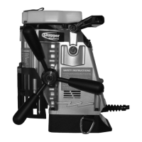
dimensions and specifications
Height 17-3/4" (450MM)
Width 8" (203MM)
Length 13-1/2" (343MM)
Weight 29 lbs. (13.15Kg)
Motor 1.75 HP 1380W (single phase)
120V / 11.5A
450 RPM (no load)
Arbor Bore 3/4"
Drill Point Breakaway 650 lbs. on
1" plate
Magnet Base Dimensions 3" x 6-3/8" (76MM X 162MM)
Magnet Dead Lift 1480 lbs. on
1" plate
Slugger Cutter Diameter (Maximum) 1-1/2"
Slugger Depth of Cut (Maximum) 2"
note: magnetic base requires 1" minimum material thickness when drill-
ing 1-1/16" and larger diameter holes
10
 Loading...