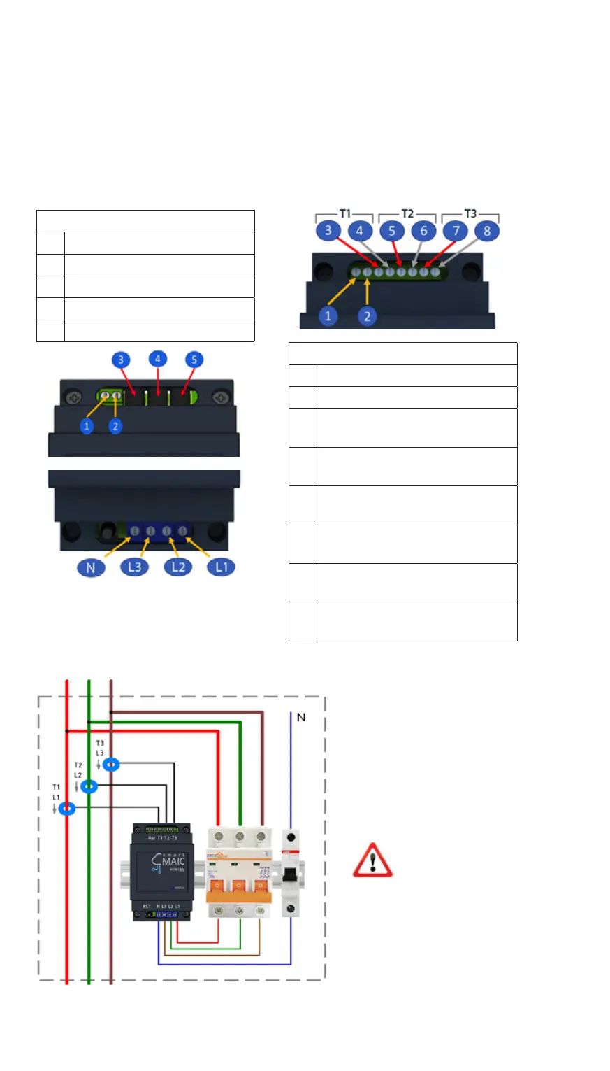
III. CONNECTION DIAGRAMS
Conditional connection diagram in a 3-phase network
Connection diagrams of current transformers and power lines for
different device modifications
A WARNING:
Do not put
unconnected
current transformers
on the wire.
This can damage
the transformers.
Upper contact group
1 controlled output
2 controlled output
3 current transformer No. 1,
red wire
4 current transformer No. 1,
black wire
5 current transformer No. 2,
red wire
6 current transformer No. 2,
black wire
7 current transformer No. 3,
red wire
8 current transformer No. 3,
black wire
Connecting transformers
to Jack 3.5 connectors
Upper contact group
1 controlled output
2 controlled output
3 current transformer No. 1
4 current transformer No. 2
5 current transformer No. 3
Lower contact group
General connection diagram
to consumer
Zero
Phase 3 Phase 2
Phase 1
Transformers 100A and Rogowski rings
1000A / 1500A / 2000A
6
USER MANUAL