HGM400N Series Genset Controller User Manual Page 16 of 38
6 CONNECTIONS
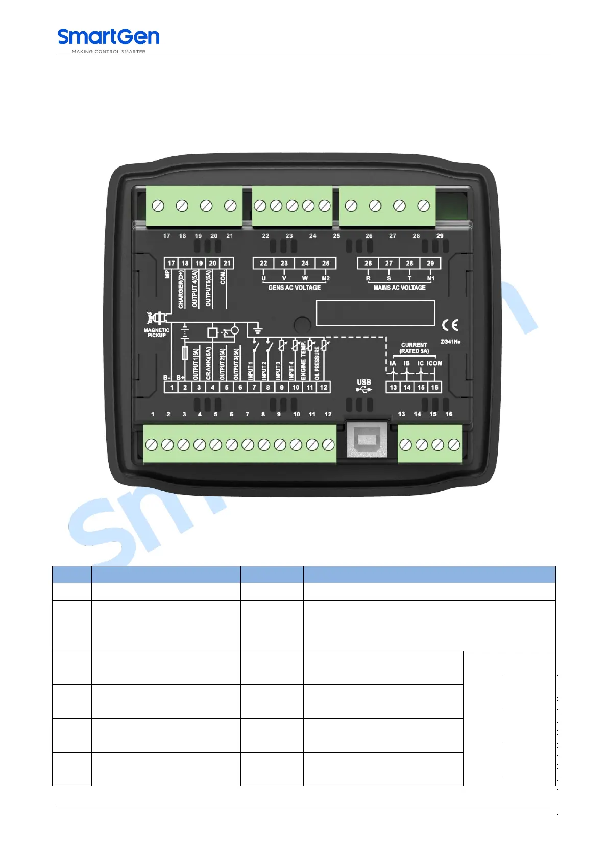
Compared with HGM420N, HGM410N has no Mains Voltage 3-phase input terminals. The rear panel of
HGM420N is as below.
Fig.2 Controller Rear Panel
Table 6 Terminal Connection Description
Connected with negative of starter battery.
Connected with positive of starter battery. If wire
length is over 30m, better to double wires in parallel.
Max. 20A fuse is recommended.
B+ is supplied by 2 point, rated
5A.
For details please
see Table 2.
B+ is supplied by 2 point, rated
5A.
B+ is supplied by 2 point, rated
5A.
B+ is supplied by 2 point, rated
5A.
 Loading...