Step-by-Step Instructions
1. Disconnect the power for the existing switches at the circuit breaker or fuse panel.
Verify that the power has been removed by trying to turn on the lights controlled by
the switches.
2. Remove the trim plate from the existing switches.
3. Unscrew and pull the existing switches from the wall box.
4. Disconnect the wires from the existing switches.
5. If the SwitchLinc is being installed into a 3/4/5-way cir-
cuit, the SwitchLinc Multi-way Companion Switch must be
installed in the wall box where power comes into the cir-
cuit. Follow the instructions included with the Multi-way Companion Switch to iden-
tify the "Hot," "Neutral," "Ground," and "Traveler" wires.
6. Before making any connections to SwitchLinc, gently pull the Set Button until a
click is heard. This will open the “air gap” and isolate the SwitchLinc from the
electricity when the circuit breaker is turned back on.
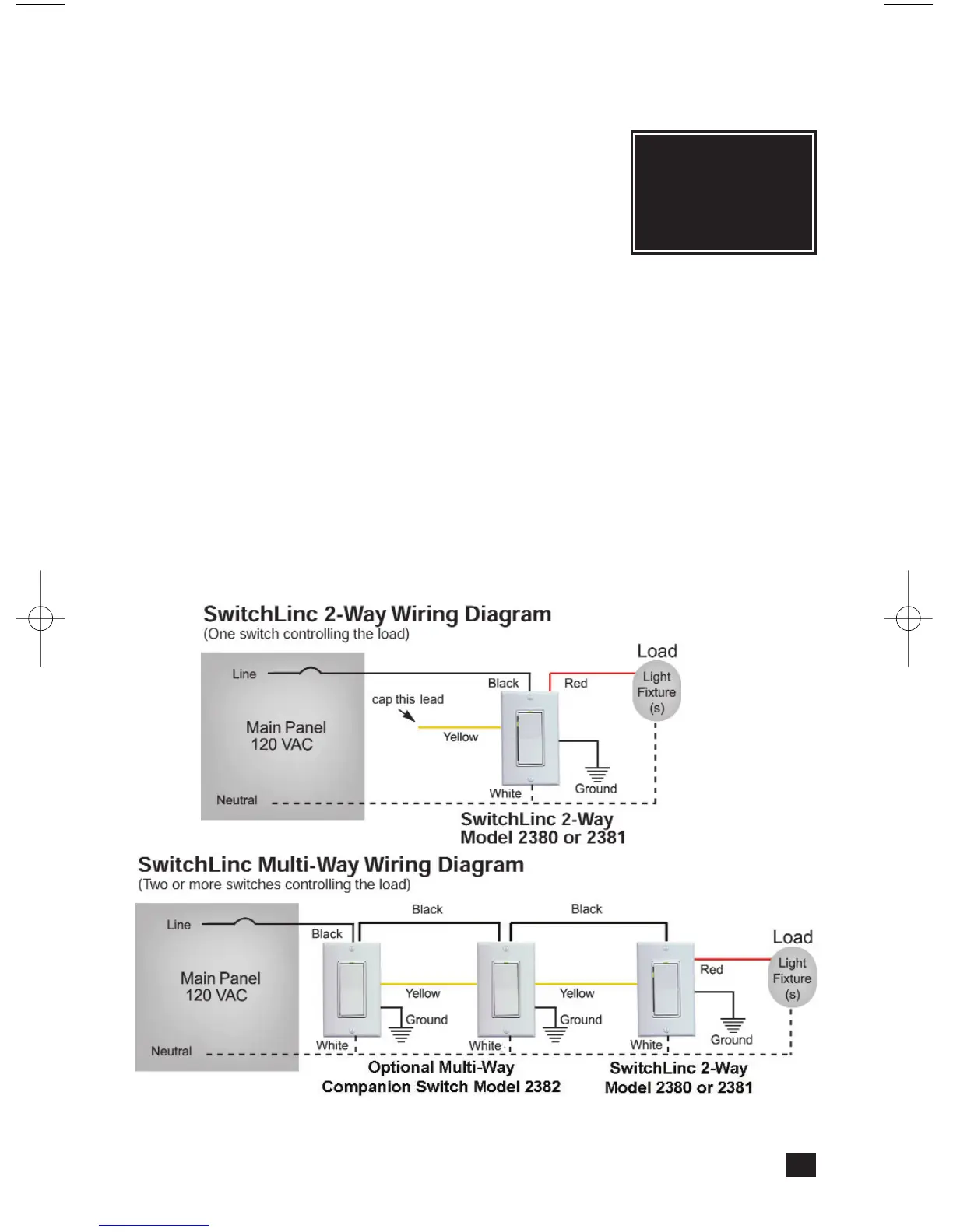
7. Orient SwitchLinc so the LED is at the top and make connections according to the
“SwitchLinc Wiring Diagram” below. Wire Multi-way Companion Switches (if used)
according to the “SwitchLinc Multi-Way Wiring Diagram” below.
8. After all connections have been made, ensure that all wire connectors are firmly
attached and that there is no exposed copper except for the Ground wire.
9. Gently place the wires and switch into the wall box (with LED at top) and screw into
place.
10. Turn the circuit breaker back on.
11. Restore power to the circuit by pressing in the SwitchLinc’s Status LED/ Set Button
top until it is even with the front plastic trim ring. SwitchLinc will be operational
when the green Status LED will comes on.
12. After testing SwitchLinc for proper operation, install the faceplate (sold separately).
5
Note: When installing multiple SwitchLinc Dimmers in a J-box, or many on the same
circuit breaker, please see specifications at the end of this manual for
limitations and recommendations.
Tip:
For additional
help installing 3-way
circuits, see page 5 in
the Multi-way
Companion Switch
manual.