Technical Data
Control unit box
Instruction manual EBF / EBF ECO page 6 of 19
11/2014
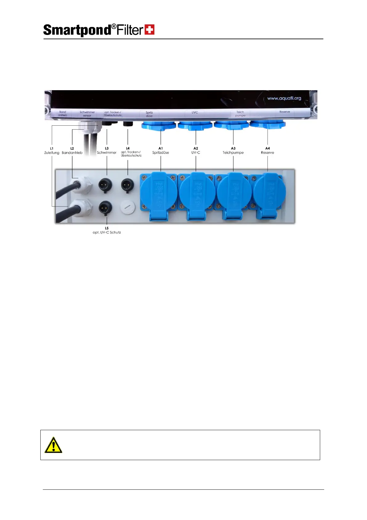
Lower side of the control unit box
At the lower side of the control cabinet, the cable outputs are visible on
the left side (L1 – L5):
L1
Lead for control unit box
Please insert in a 220VAC socket, which is secured with a FI protective
switch.
This cable is connected with the 24VDC motor in the motor box through
the 2 pole crimp connector.
With this 2 pole connector, the float gauge level B1 is connected through
the soldered 2 pole socket (insert and tighten the connecting nuts
securely).
L4
Option: Dry running/
Overflow protection
When the option ‘‘Dry running / Overflow protection’’ is selected, the
float gauge B4 is connected with this 2 pole connector through the pole
soldered socket (insert and tighten the connecting nuts securely).
When the option UVC-circuit is ordered, the protective switch B2 is
connected with this 2 pole connector through the soldered 2-pole socket
(insert and tighten the connecting nuts securely).
When the leads L3 to L5 are plugged in, it shall be made sure that the
correct signal generator (float gauge, switch etc.) is connected to the
respective connector.