Technical Data
Control unit box
Instruction manual EBF / EBF ECO page 7 of 19
11/2014
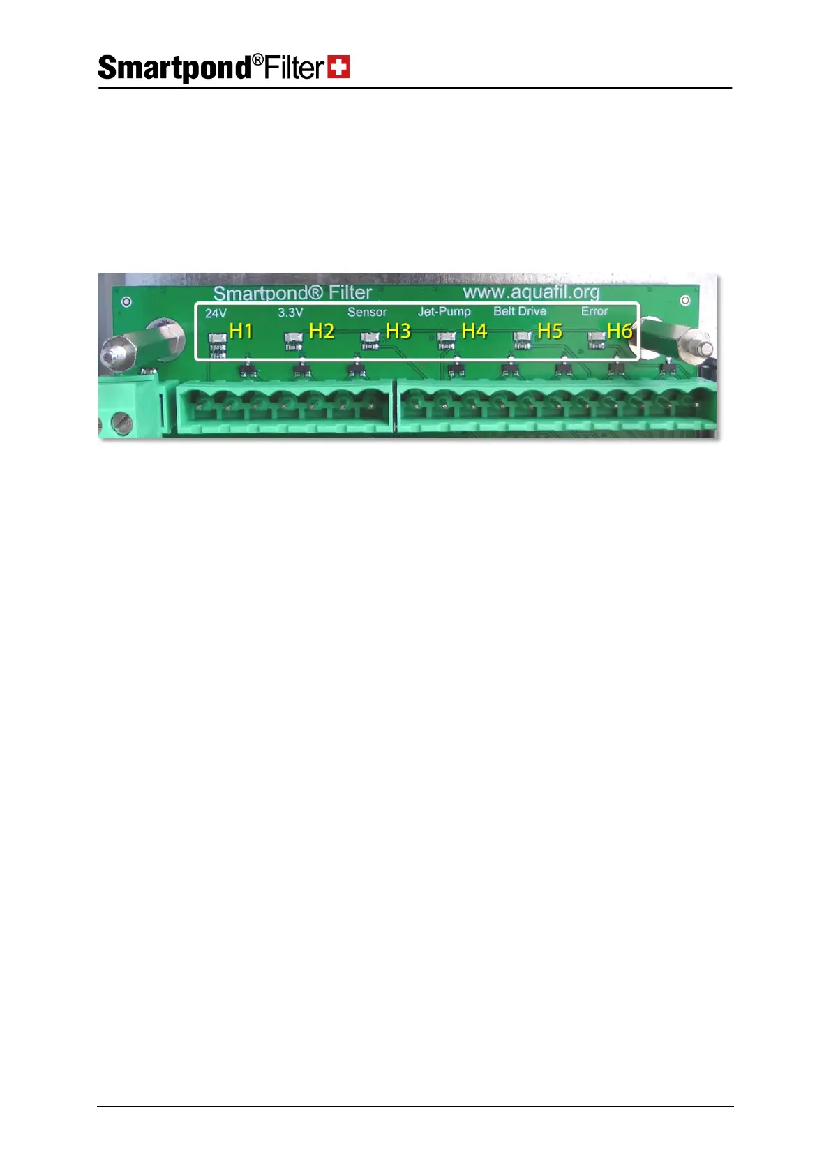
2.1.4 Control unit circuit board
On the control unit circuit board, several LEDs (H1-H6) are available for
control purposes. They are visible all the time through the closed
transparent cover of the control unit box:
Supply voltage 24VDC
(must light up during operation)
Internal circuit board voltage 3.3VDC
(must light up during operation)
Lights green when the float gauge sensor (B1) is active.
Lights green when the power socket output for ‘‘spraying pump’’ is
triggered/activated.
Lights green when the output for belt drive is triggered.
Lights red when the belt drive motor overloads (after 5 attempts).
Reset error by pushing the manual control (push button T1 – page 5)