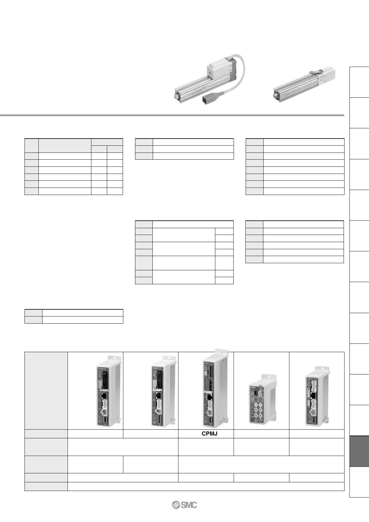
Compatible Controllers/Driver
Type
Step data
input type
Step data
input type
CC-Link
direct
input
type
Programless type Pulse input type
Series
LECP6 LECA6 LECPMJ LECP1 LECPA
Features
Value (Step data) input
Standard controller
CC-Link direct input
Capable of setting up operation
(step data) without using a
PC or teaching box
Operation by
pulse signals
Compatible motor
Step motor
(Servo/24 VDC)
Servo motor
(24 VDC)
Step motor
(Servo/24 VDC)
Maximum number of step data
64 points 64 points 14 points —
Power supply voltage
24 VDC
* Copper and zinc materials are used for the motors, cables, controllers/drivers.
*
Specifications and dimensions for the 25A-series are the same as standard products.
158
Electric Actuator/Rod Type
Series 25A-LEY
Nil
D
Screw mounting
DIN rail mounting
*
1
*
Produced upon receipt of order (Robotic cable only)
*1 Mounting bracket is shipped together, (but
not assembled).
*2 For horizontal cantilever mounting with the
rod flange, head flange and ends tapped,
use the actuator within the following stroke
range.
· LEY25: 200 or less
· LEY32/40: 100 or less
*3 For mounting with the double clevis, use the
actuator within the following stroke range.
· LEY16: 100 or less
· LEY25: 200 or less
· LEY32/40: 200 or less
*4 H e ad fl a nge is not avai l ab l e for the
LEY32/40.
*1 For details about controllers/driver and
compatible motors, refer to the compatible
controllers/driver below.
*2 Only available for the motor type “Step
motor”.
*3 Not applicable to CE.
*4 When pulse signals are open collector, order
the current limit resistor (LEC-PA-R-)
separately.
*1 DIN rail is not included. Order it separately.
i Mounting
*
1
o Actuator cable type
*
1
!0 Actuator cable length [m]
!1 Controller/Driver type
*
1
!2
I/O cable length [m]
*
1
, Communication plug
!3 Controller/Driver mounting
Motor mounting position:
Top/Parallel
*1 The standard cable should be used on fixed
parts. For using on moving parts, select the
robotic cable.
*2 Only available for the motor type “Step
motor”.
*1 When “Without controller/driver” is selected
for controller/driver types, I/O cable cannot
be selected. Refer to the catalog CAT. E102
if I/O cable is required.
*2 When “Pulse input type” is selected for
controller/driver types, pulse input usable
only with differential. Only 1.5 m cables
usable with open collector.
*3 When “CC-Link direct input type” is selected
for controller/driver types, I/O cable is not
included. Only “Nil”, “S” or “T” can be
selected.
Motor mounting position:
In-line
Nil
Without controller/driver
6N
LECP6/LECA6
(Step data input type)
NPN
6P
PNP
1N
LECP1
*
2
(Programless type)
NPN
1P
PNP
MJ
LECPMJ
*
2
*
3
(CC-Link direct input type)
—
AN
LECPA
*
2
*
4
(Pulse input type)
NPN
AP
PNP
Symbol
Type
Motor mounting position
Top/Parallel
In-line
Nil
Ends tapped (Standard)
*
2
U
Body bottom tapped
L
Foot
—
F
Rod flange
*
2
G
Head flange
*
2
*
4
—
D
Double clevis
*
3
—
Nil
Without cable
S
Standard cable
*
2
R
Robotic cable (Flexible cable)
Nil
Without cable
1
1.5
3
3
5
5
8
8
*
A
10
*
B
15
*
C
20
*
Nil
Without cable (Without communication plug connector
*
3
)
1
1.5
3
3
*
2
5
5
*
2
S
Straight type communication plug connector
*
3
T
T-branch type communication plug connector
*
3
25A-P-B-P158-web修正-CS3e.indd 158 14.9.11 5:55:39 PM

 Loading...