LEY25, 32
* Applicable stroke table
* Consult with SMC for non-standard strokes as they are produced as special orders.
w Size
* Refer to the table below for details.
y Stroke [mm]
*
When “With lock” is selected for the top mounting and right/
left side parallel types, the motor body will stick out of the
end of the body for size 25 with strokes 30 or less. Check
for interference with workpieces before selecting a model.
u Motor option
i Rod end thread
e
Motor mounting position
*1 Mounting bracket is shipped together, (but not
assembled).
*2 For horizontal cantilever mounting with the rod
flange, head flange and ends tapped, use the
actuator within the following stroke range.
· LEY25: 200 or less · LEY32: 100 or less
*3 For mounting with the double clevis, use the
actuator within the following stroke range.
· LEY25: 200 or less · LEY32: 200 or less
*4 Rod flange is not available for the LEY25 with
stroke 30 and motor option “With lock”.
*5 Head flange is not available for the LEY32.
*
The values shown in ( ) are the lead for size 32 top
mounting, right/left side parallel types. (Equivalent
lead which includes the pulley ratio [1.25:1])
t Lead [mm]
Electric Actuator/Rod Type
25, 32
Size
o Mounting
*
1
r Motor type
*
1
*1 For motor type “S2” and “S6”, the compatible driver part number suffixes are “S1” and “S5”
respectively.
*2 For details about the driver, refer to the WEB catalog.
Standard
Symbol
Type Output [W] Actuator size
Compatible drivers
*
2
S2
AC servo motor
(Incremental encoder)
100 25 LECSA-S1
S3
AC servo motor
(Incremental encoder)
200 32 LECSA-S3
S6
AC servo motor
(Absolute encoder)
100 25
LECSB-S5
LECSC-S5
LECSS-S5
S7
AC servo motor
(Absolute encoder)
200 32
LECSB-S7
LECSC-S7
LECSS-S7
Symbol
Type
Motor mounting position
Top/Parallel
In-line
Nil
Ends tapped (Standard)
*
2
U
Body bottom tapped
L
Foot
—
F
Rod flange
*
2
*
4
G
Head flange
*
2
*
5
—
D
Double clevis
*
3
—
Symbol
LEY25 LEY32
*
A
12 16 (20)
B
6 8 (10)
C
3 4 (5)
Nil
Top mounting
R
Right side parallel
L
Left side parallel
D
In-line
Nil
Female rod end
M
Male rod end
(1 rod end nut is included.)
Nil
Without option
B
With lock
*
30
30
to
to
500
500
Stroke
[mm]
Model
30 50 100 150 200 250 300 350 400 450 500
Manufacturable
stroke range [mm]
LEY25
— — 15 to 400
LEY32
20 to 500
25
32
Solid state auto switches should be ordered separately.
For details about auto switches, refer to page 164.
Applicable auto switches
D-M9N(V)-900, D-M9P(V)-900, D-M9B(V)-900
D-M9NW(V)-900, D-M9PW(V)-900, D-M9BW(V)-900
Mounting Bracket Part No. for Series 25A-
*1 When ordering foot brackets, order 2 pieces per actuator.
*2 Parts belonging to each bracket are as follows.
Foot, Flange: Body mounting bolt, Double clevis: Clevis pin, Type C retaining ring for axis,
Body mounting bolt
Applicable size
Foot
*
1
Flange Double clevis
25
25-LEY-L025 25-LEY-F025 25-LEY-D025
32
25-LEY-L032 25-LEY-F032 25-LEY-D032
Surface
treatment
RAYDENT
®
RAYDENT
®
Coating
(Size 16: Electroless nickel plating)
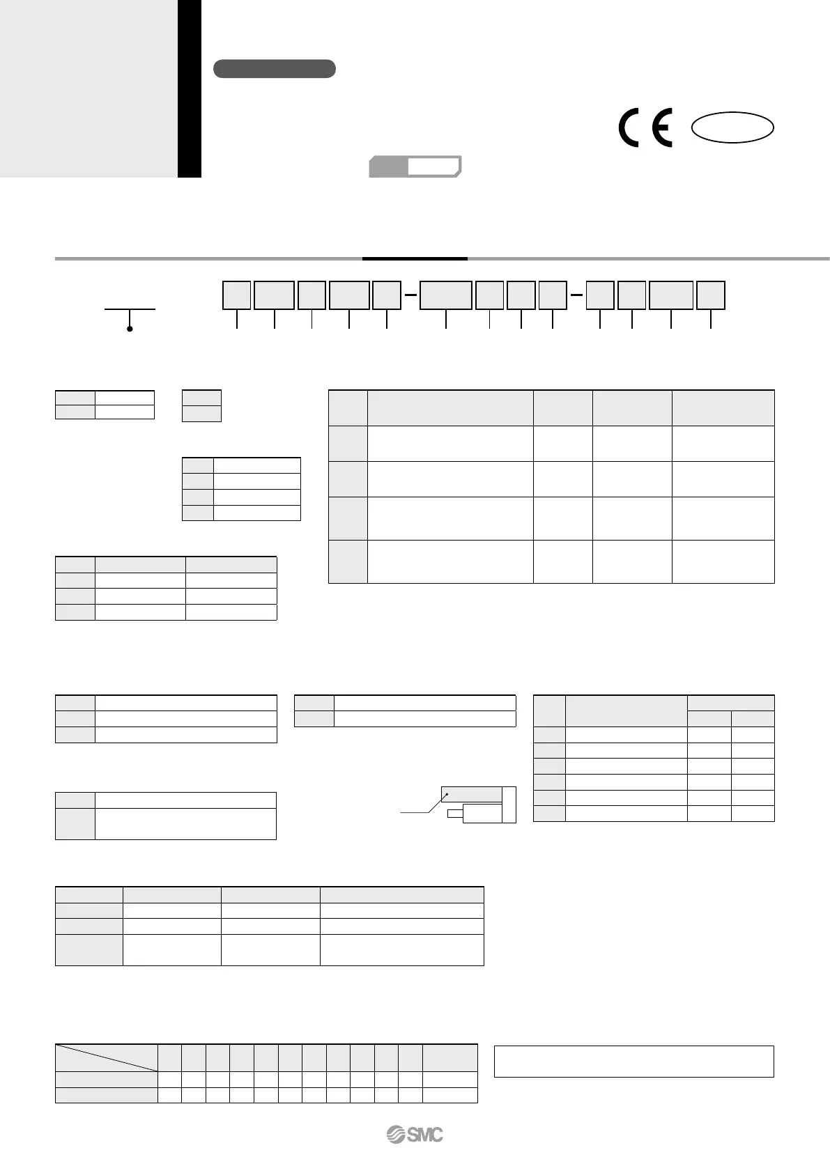
Series
25A-LEY
25A-LEY
25 100
BH 2 A1S
w e r tq y u i o !0 !1 !2 !3
S2
q Accuracy
Nil
Basic type
H
High precision type
25A-P-B-P159-webA-CS3e.indd 159 15.2.13 2:05:19 PM

 Loading...