-11-
No.D-※S-OMJ0004-E
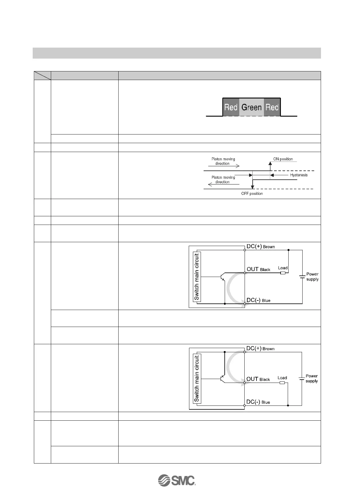
■Definition and terminology
A type of indicating methods
which lights up the Red LED light
up when the Auto switch comes
to the operating position, and
lights up the Green LED when
the Auto switch comes to the
optimum operating position.
Auto switch which has only signal line and COM line.
The current flowing to the load when the Auto switch turns off.
The difference between the
points when the Auto switch
turns on and off, which is
provided to prevent
chattering.
The voltage applied between the COM and signal line when the Auto switch turns
on.
The current flowing to the load when the Auto switch turns on.
The center position of the sensor unit (which gets the strongest reaction of the
sensor unit), which means the center position of an operating range as well.
Auto switch which sinks
current from the signal
line when turning on.
: This circuit diagram is a
sample.
Normally open
(normal direction) output
When magnetic force is detected, the output signal turns ON.
Normally closed
(inverted) output
When magnetic force is not detected, the output signal turns ON.
Auto switch which
sources current from the
signal line when turning
on.
: This circuit diagram is a
sample.
Auto switch which generates on and off outputs with a mechanical contact.
Sequence controller
(PLC)
The device to perform sequence control, which performs controlling such as receipt
of inputs from the Auto switch along with programming and sending of the output to
other machines.
Auto switch which generates on and off outputs with or without mechanical contact
such as a transistor.
 Loading...