-24-
No.D-※S-OMJ0004-E
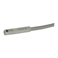
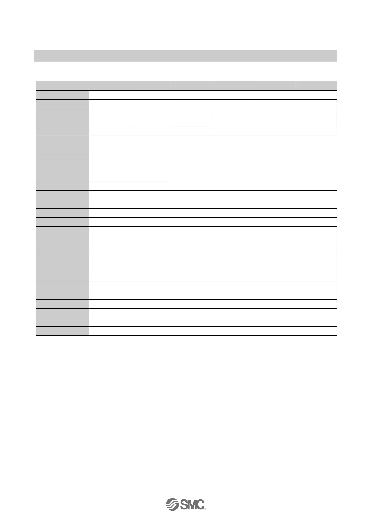
•D-M9BW(V)/D-M9NW(V)/D-M9PW(V)
PLC: Programmable Logic Controller
5/12/24 VDC (4.5 to 28 VDC)
0.8 V or less at load current of 10 mA
(2 V or less at load current of 40 mA)
Operating position: The Red LED turns ON
Optimum operating position: The Green LED turns ON
Vinyl sheath cable
2.6, 0.15 mm
2
, 2-wire (D-M9BW(V)), 3-wire (D-M9NW(V),D-M9PW(V))
50 MΩ or more under the test voltage 500 VDC (between case and cable)
1000 VAC 1 min. (between case and cable)
IEC 60529 criteria IP67, JISC0920 watertight construction
 Loading...