-53-
EX※※-OMR1012
When configuring the input and output data size, please ensure the following steps are taken;
•The minimum value of both the input and output data size is 2 bytes.
If the EX600 data size is 0 or 1byte, this must be set to 2 bytes.
•If the input or output size is an odd number, add 1 byte, to make it an even number of bytes.
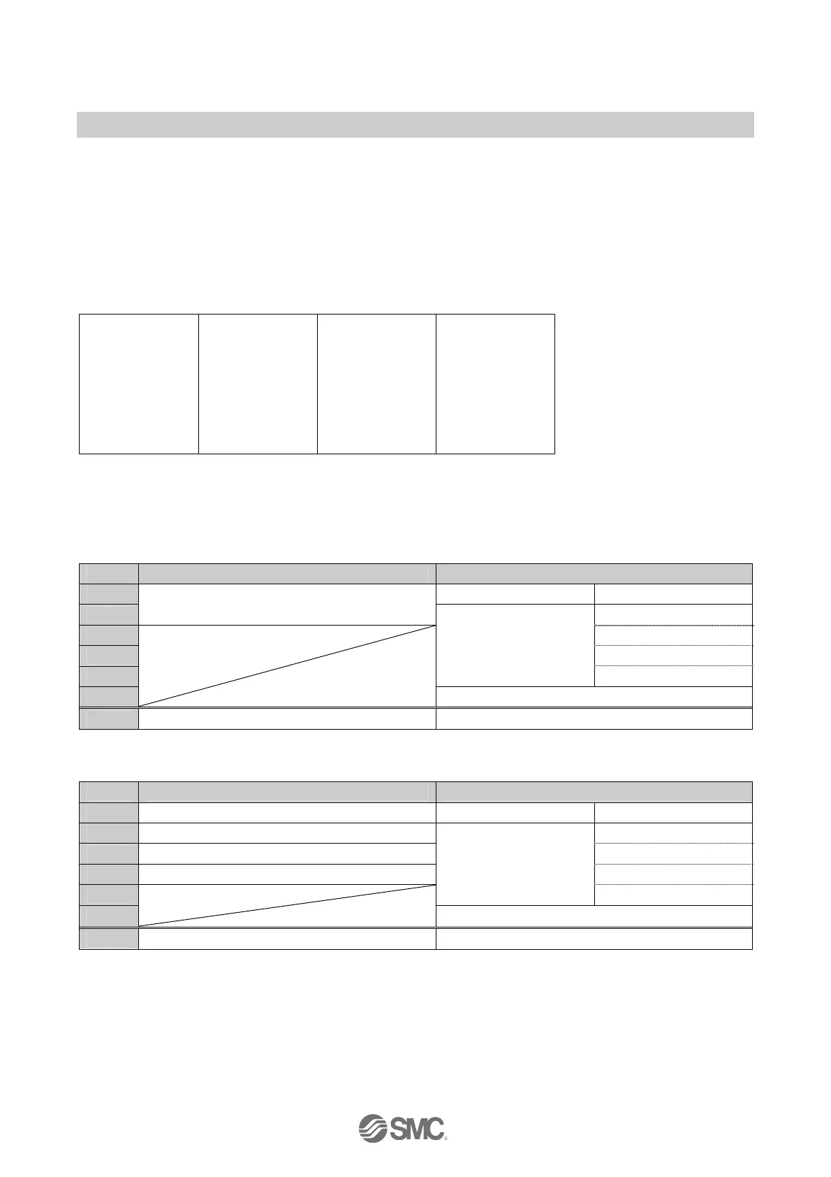
The I/O map is shown with the following unit configuration as an example.
<Example 1>
Unit 0 Unit 1
End plate
DY□B
Digital output
unit
1 byte output
SEN5
SI unit
4 bytes output
Valve
Input data: None
Output data: (Unit 0) Digital output Unit (EX600-DY□B): 1 byte occupied
(Unit 1) SI Unit (EX600-SEN5): 4 bytes occupied
•When Diagnostic mode 0 is selected
Input data Output data
Byte0 DY□B (Unit 0) Output 0 to 7
Byte1
Padding data
Output 0 to 7
Byte2 Output 8 to 15
Byte3 Output 16 to 23
Byte4
SEN5 (Unit 1)
Output 24 to 31
Byte5
Padding data
Total 2 bytes 6 bytes
•When Diagnostic mode 1 is selected
Input data Output data
Byte0 Diagnostic data byte0 DY□B (Unit 0) Output 0 to 7
Byte1 Diagnostic data byte1 Output 0 to 7
Byte2 Diagnostic data byte2 Output 8 to 15
Byte3 Diagnostic data byte3 Output 16 to 23
Byte4
SEN5 (Unit 1)
Output 24 to 31
Byte5
Padding data
Total 4 bytes 6 bytes

 Loading...