-54-
EX※※-OMR1012
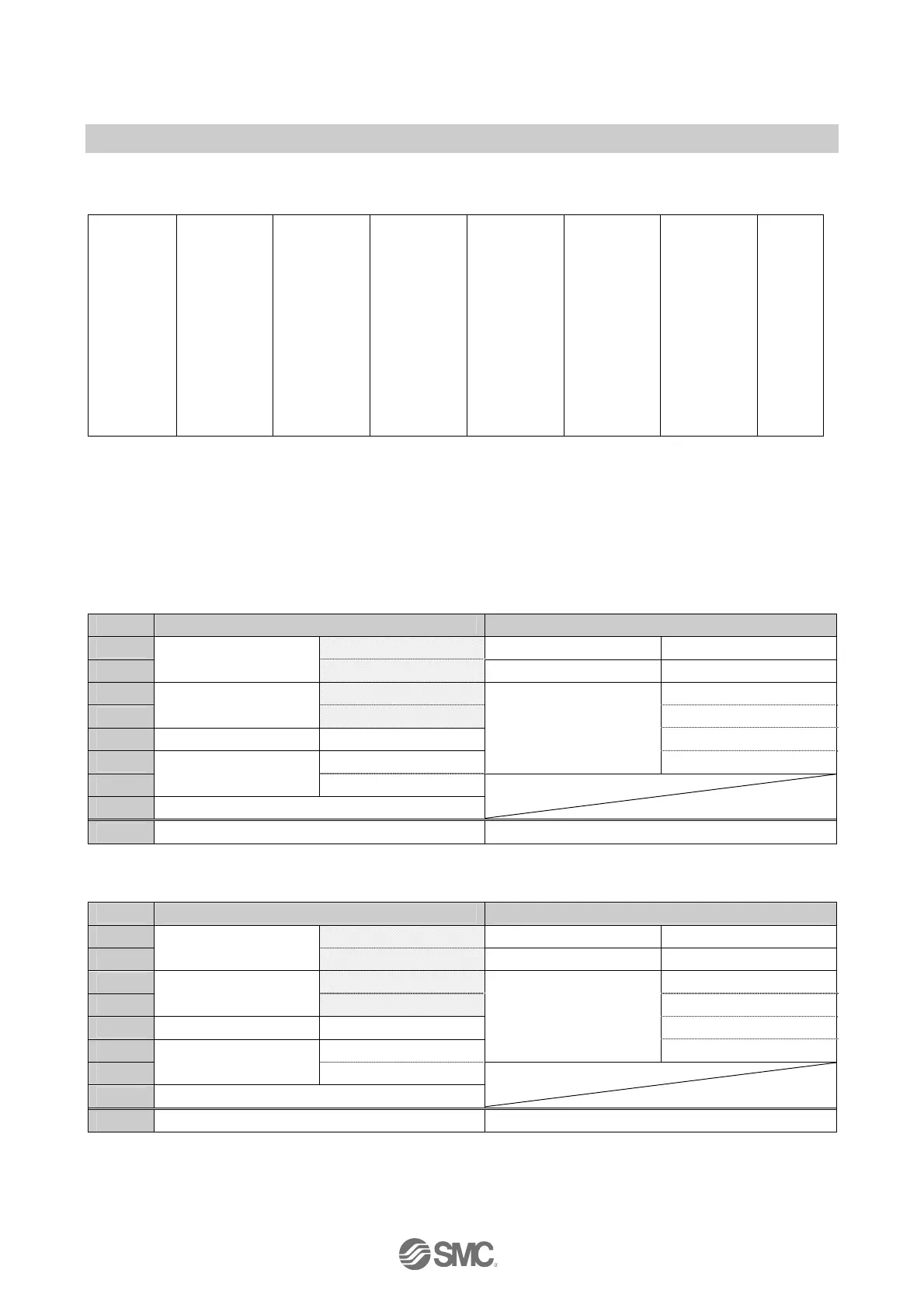
<Example 2>
Unit 0 Unit 1 Unit 2 Unit 3 Unit 4 Unit 5
End plate
AXA
Analogue
input
4 byte
Input
DY□B
Digital
output
1 byte
Output
DY□B
Digital
output
1 byte
Output
DX□B
Digital
input
1 byte
Input
DX□D
Digital
input
2 byte
Input
SEN5
SI unit
4 byte
Output
Valve
Input data: (Unit 0) Analogue input Unit (EX600-AXA): 4 bytes occupied
(Unit 3) Digital input Unit (EX600-DX□B): 1 byte occupied
(Unit 4) Digital input Unit (EX600-DX□D): 2 bytes occupied
Output data: (Unit 1) Digital output Unit (EX600-DY□B): 1 byte occupied
(Unit 2) Digital output Unit (EX600-DY□B): 1 byte occupied
(Unit 5) SI Unit (EX600-SEN5): 4 bytes occupied
•When Diagnostic mode 0 and byte order of analogue value LSB-MSB are selected.
Input data Output data
Byte0
Lo byte
DY□B (Unit 1) Output 0 to 7
Byte1
AXA channel 0
(Unit 0)
Hi byte
DY□B (Unit 2) Output 0 to 7
Byte2
Lo byte
Output 0 to 7
Byte3
AXA channel 1
(Unit 0)
Hi byte
Output 8 to 15
Byte4 DX□B (Unit 3) Input 0 to 7 Output 16 to 23
Byte5 Input 0 to 7
SEN5 (Unit 5)
Output 24 to 31
Byte6
DX□D (Unit 4)
Input 8 to 15
Byte7 Padding data
Total 8 bytes 6 bytes
•When Diagnostic mode 0 and byte order of analogue value MSB-LSB are selected.
Input data Output data
Byte0
Hi byte
DY□B (Unit 1) Output 0 to 7
Byte1
AXA channel 0
(Unit 0)
Lo byte
DY□B (Unit 2) Output 0 to 7
Byte2
Hi byte
Output 0 to 7
Byte3
AXA channel 1
(Unit 0)
Lo byte
Output 8 to 15
Byte4 DX□B (Unit 3) Input 0 to 7 Output 16 to 23
Byte5 Input 0 to 7
SEN5 (Unit 5)
Output 24 to 31
Byte6
DX□D (Unit 4)
Input 8 to 15
Byte7 Padding data
Total 8 bytes 6 bytes

 Loading...