C
HAPTER
1
| Introduction
Description of Hardware
– 30 –
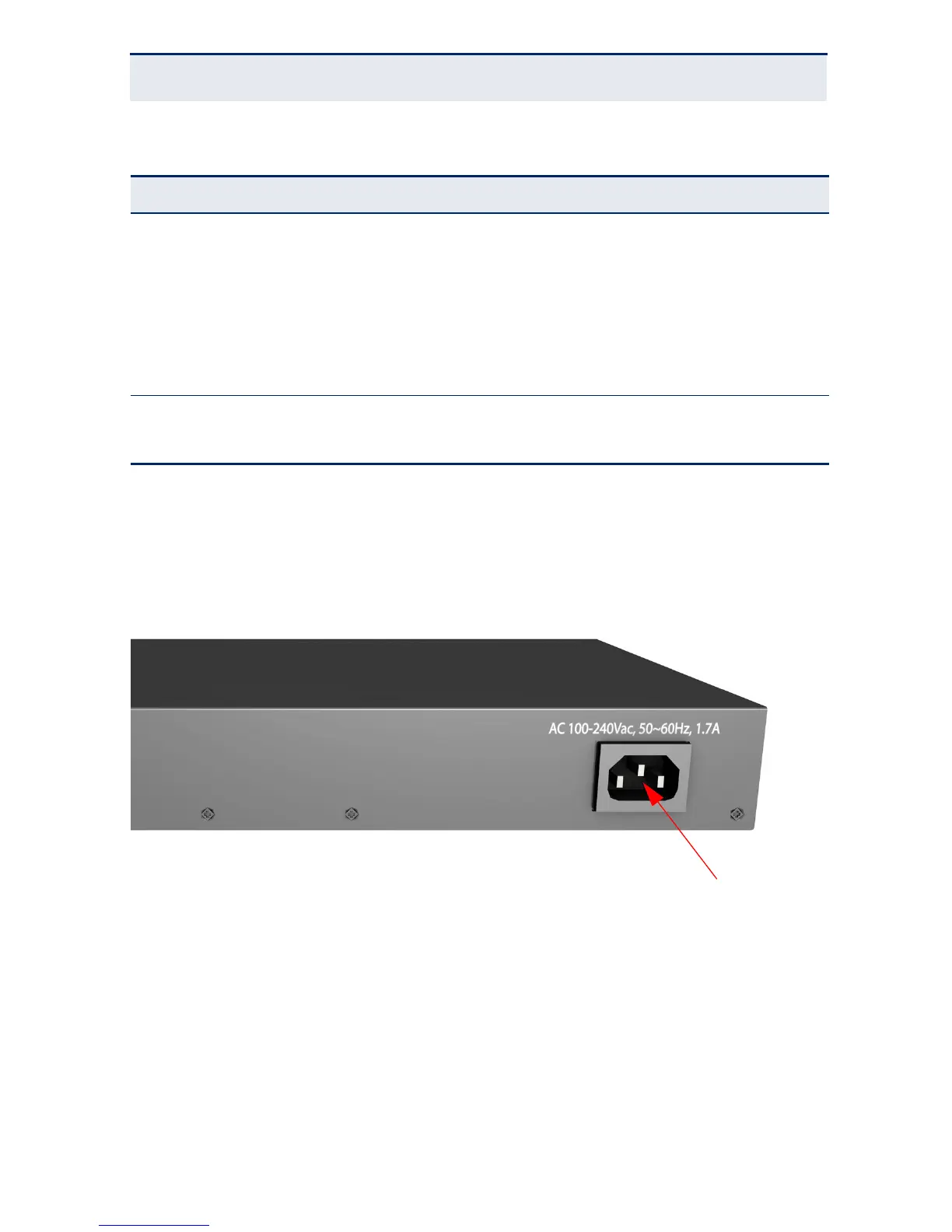
POWER SUPPLY INLET
There is one power inlet on the rear panel of the switch. The standard power
inlet is for the AC power cord.
Figure 4: Power Supply Inlet
GROUNDING POINT
To prevent accidental electrical shock or damage to your switch, it is
recommended that you ground the switch to an earth point by attaching a
grounding wire (not supplied) to the grounding point located on the rear panel,
with a metal screw. If located in a tall building, grounding points include metal
Diag On Green The system diagnostic test has completed successfully.
Flashing
Green
The system boot up is in progress.
On Amber /
Flashing
Amber
The system diagnostic test is in progress.
Off The system diagnostic has completed.
PoE On Amber Powered device connected.
Off No powered device connected.
Table 3: System Status LEDs
LED Condition Status
 Loading...