HEC-OM-O018-A
Chapter 2 Description and Function of Each Part
1.5 Safety Interlocks
2-1
Chapter 2 Description and Function of
Each Part
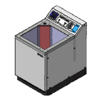
Fig. 2 Thermo Electric Bath
Table 2 Thermo Electric Bath
No. Description Function
①
Contoroller Various displays are shown and settings are input.
②
Main power switch
(Circuit protector)
Main power ON/OFF of product.
③
ALARM LED(Red)
Lights up when an alarm occurred.
For details, refer to page 5-14 “5.2.1 Content of Alarms”,
Table5-3.
④
RUN LED(Green)
Lights up while the product is running.
⑤
Bath Vessel to store the bath liquid.
⑥
Power supply connector
(AC)
IEC 60320 C14 connector.
⑦
Communication connector
(COMMUNICATION)
Connector for RS-485(-733/-734/-736/-748) or
RS-232C(-745/-746/-747/-749) serial communication.
⑧
Alarm output connector
(ALARM)
Connector for contact signals for alarms.
For details, refer to page5-14 Content of Alarms”, Table5-3.
⑨
Facility Water outlet port Facility water outlet port, connection size is Rc3/8.
⑩
Facility Water inlet port Facility Water inlet port, connection size is Rc3/8.
⑪
Drain port CPC coupling PLCD 16004
⑫
Strainer Prevents clogging the pump suction port.
⑬
Level switch connector Use to connect level switch (Option)
①
④
③
②
⑤
⑫
⑥
⑦
⑧
⑬
⑨
⑩
⑪

 Loading...