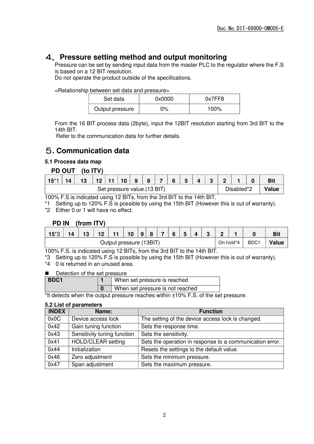
4.Pressure setting method and output monitoring
Pressure can be set by sending input data from the master PLC to the regulator where the F.S
is based on a 12 BIT resolution.
Do not operate the product outside of the specifications.
<Relationship between set data and pressure>
From the 16 BIT process data (2byte), input the 12BIT resolution starting from 3rd BIT to the
14th BIT.
Refer to the communication data for further details.
5. Communication data
5.1 Process data map
PD OUT (to ITV)
Set pressure value.(13 BIT)
100% F.S.is indicated using 12 BITs, from the 3rd BIT to the 14th BIT.
*1 Setting up to 120% F.S is possible by using the 15th BIT (However this is out of warranty).
*2 Either 0 or 1 will have no effect.
PD IN (from ITV)
100% F.S. is indicated using 12 BITs, from the 3rd BIT to the 14th BIT.
*3 Setting up to 120% F.S is possible by using the 15th BIT (However this is out of warranty).
*4 0 is returned in an unused area.
Detection of the set pressure
When set pressure is reached
When set pressure is not reached
*It detects when the output pressure reaches within ±10% F.S. of the set pressure.
5.2 List of parameters
The setting of the device access lock is changed.
Sensitivity tuning function
Sets the operation in response to a communication error.
Resets the settings to the default value.
Sets the minimum pressure.
Sets the maximum pressure.
2020-11-0216:16
DI156249

 Loading...