30
EEWB331B
As a result reading is II - Un.7 or Un.7 - II
Option 2: Abort optimization
• Press the ST
OP key (5) to exit the OP program and
return to the balancing program.
The imbalance on the wheel is shown on the readout.
• Balance the wheel according to the readings.
Weight minimization program cycle
If the rim compensation run was omitted and the FINE
key (3) was pressed to go directly into the minimization
program (reading U
n.), proceed as follows.
• Clamp the wheel.
• Position the valve exactly perpendicular to and
above the main shaft.
• Press the ENTER key (1) to acquire the valve
position.
Reading Un.4 appears (Fig. 34).
• Spin the wheel (START).
The measuring run is carried out. After the measuring
run two readings are possible:
Un.5 - H1
Further minimization is not recommended, but is possible.
Un.5 – I (1 Reference mark
Fig. 35)
Continue with the UN program.
Reading Un.5 - H1
If Un.5 - H1 appears, further minimization is not
recommended since the measurement values do not
exceed the limit values. However, it is possible to
continue minimization so as to achieve an improvement,
if only slight (e.g.: for critical vehicles).
To continue minimization:
• Proceed as indicated for reading Un.5 – I.
T
o abort minimization:
• Press the STOP key (5) to return to the balancing
program and balance the wheel according to the
readings.
Reading Un.5 – I (1 Reference mark
Fig. 35)
• After the measuring run readjust the wheel according
to the direction indicator and make a chalk mark (Fig.
36) on the right side of the tire exactly perpendicular
to and above the main shaft.
• Readjust the tire on the rim so that the mark
coincides with the valve (use the tire changer Fig.
37).
• Clamp the wheel on the balancer and readjust it so
that
the valve is exactly perpendicular to and above
the main shaft.
• Press the E
NTER key (1) to acquire the valve
position.
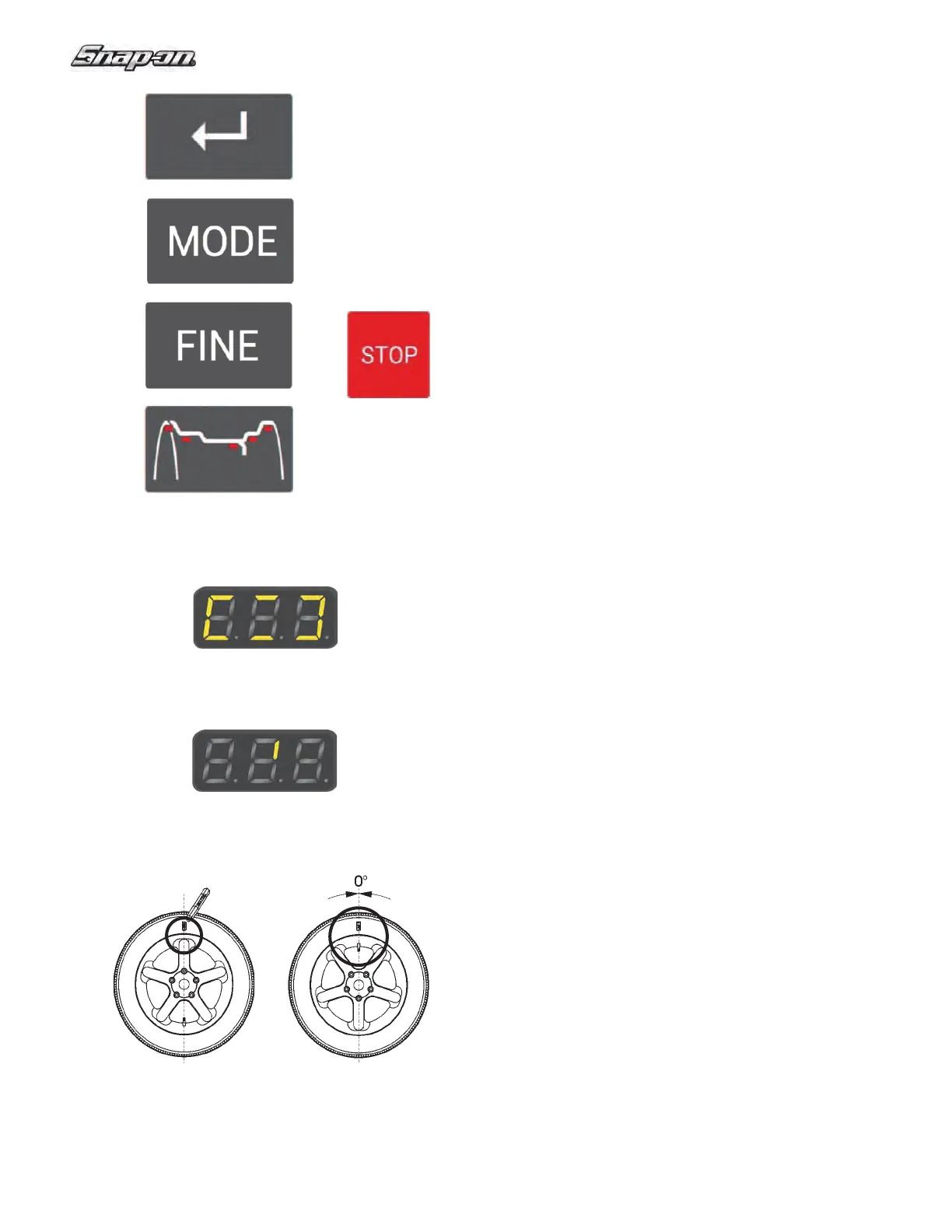
1
2
3
4
5
Figure 32
Figure 34
Figure 35
Figure 36 Figure 37