Do you have a question about the Snap-On EEWB330B and is the answer not in the manual?
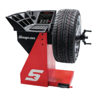
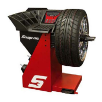
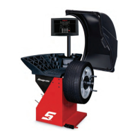
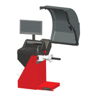
Overview of the EEWB330B computer wheel balancer and manual usage.
Important information concerning safety and maintenance of the balancer.
Details the intended use and limitations for car, light truck, and motorcycles wheels.
Technical specifications of the EEWB330B digital wheel balancer.
Key functionalities and benefits of the EEWB330B wheel balancer.
List of accessories included with the EEWB330B wheel balancer.
List of optional accessories available for the EEWB330B.
Physical dimensions and footprint requirements for the wheel balancer.
Specifies the recommended working space and environmental conditions for installation.
Guidance on safely removing and positioning the wheel balancer during installation.
Steps for mounting the shaft adapter and accessories onto the balancer.
Procedure for connecting the wheel balancer to the power supply.
Explanation of terms and components for operating the wheel balancer.
Description and function of each key on the balancer's input panel.
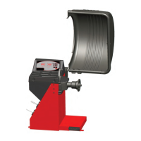
Details components of the wheel balancer cabinet, including display and storage.
General sequence of operations for balancing a wheel assembly.
Pre-balancing checks for the wheel and tire assembly.
Guidance on properly mounting various types of wheels onto the balancer shaft.
Procedure for mounting light truck wheels, possibly requiring offset spacers.
Methods for mounting wheels like clad wheels requiring specific tooling.
How to select different balancing modes for optimal weight placement.
Details on choosing specific weight placement modes using the Mode button.
Correct SAPE arm positions for applying ALU adhesive weights on the rim.
Setting preferences like fine balancing, unit conversion, and rim diameter units.
Manual or automatic entry of rim distance and width for balancing.
Procedure for manually inputting rim dimensions when automatic entry fails.
Automatic recognition of weight locations using the SAPE arm for ALU wheels.
Steps for automatic rim dimension input and ALU P mode selection.
Procedure for spinning the wheel and completing the measurement cycle.
Methods for applying clip-on and stick-on weights to correct wheel imbalance.
Using the SAPE arm to apply ALU P weights accurately on the rim.
Balancing wheels with spokes, placing weights in hidden positions.
Procedure for using Split Weight Mode for balancing spoke wheels.
Procedure to verify and perform user calibration for accurate balancing.
Storing and recalling rim data (wheel type, dimensions, settings) for multiple users.
Switching the displayed weight unit between ounces and grams.
Switching measurement units for diameter and width between inches and millimeters.
Program cycle for balancing optimization and weight minimization.
Steps to continue or abort the balancing optimization process.
Interpreting readings and proceeding with optimization or tire readjustment.
Interpreting OP.8 readings, handling E9 errors, and aborting optimization.
Options for not adjusting the tire and interpreting H0/H2 readings.
Steps for weight minimization when rim compensation is omitted.
Procedures for tire readjustment based on Un.7 readings.
Interpreting Un.8 readings, handling E9 errors, and aborting minimization.
General order of operations for diagnosing and resolving balancer problems.
Understanding error (E-codes) and warning (H-codes) messages.
How to select and change operating modes using C codes.
Setting limits (C8), measuring spin counter (C12), and shaft stop (C11).
Readjustment procedures (C14) and software version info (C21).
List and troubleshooting steps for E-codes (errors).
Troubleshooting E22, E24, E25, E26, E27, E28, E50, E51, E52, E82, E92.
Understanding H-codes (warnings) related to optimization and speed.
Important safety precautions before performing maintenance or repairs.
Details the terms and conditions of the manufacturer's limited two-year warranty.
| Brand | Snap-On |
|---|---|
| Model | EEWB330B |
| Category | Wheel Balancers |
| Language | English |