14
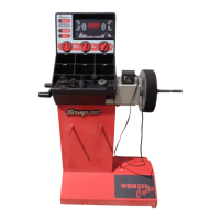
EEWB330B
4.3 MODE SELECTION
The majority of balancing
takes place in the default
2-plane
dynamic
mode
which
is
displayed as “2 PL”
(location 1). Hammer-on clip weights will be placed
on both inside and outside of the rim edge. If required,
select an optional weight placement mode by pressing
the Mode button until the appropriate placement mode
is displayed.
4.3.1 WEIGHT PLACEMENT MODES
Before Spinning the wheel (although it may be done
after
wards) choose the appropriate balancing mode
for the wheel. To select the various placement modes
press the (9) Weight Placement button (Figure 14)
until placement LEDs (Figure 14a) indicate desired
placement positions.
A. DYNAMIC (two planes), suggested for all steel rims.
In this case the wheel weights must be clipped onto the
rim edges. This function is selected as a default and
the LEDs corresponding to the wheel weight location
are lit on Figure 15.
Figure 15
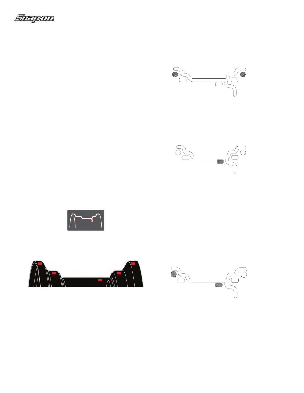
B. STATIC
(single plane - Figure 16). Suggested for
narrow rims (3” or less). Use a single corrective weight
placed in the center of rim as illustrated in Figure 16.
Figure 16
To select the STATIC Mode:
1.
Touch the SAPE arm to the rim ! ange.
2. Enter the rim width dimension.
3. Press four times Alu button (9).
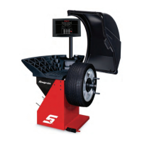
WEIGHT COMBINATION MODES USING THE
WEIGHT SELECTION BUTTON
See (Figure 14). Pressing the weight selection button
(9) will toggle the LED’s to the weight default selections
as shown. Balancing using a combination of hammer-on
and adhesive weights as shown in Figure 17.
Figure 17
Figure 14a
9
Figure 14