10
EEWB330B
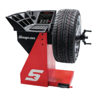
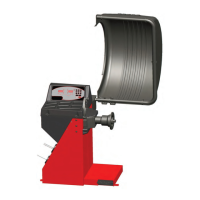
3.0 TERMINOLOGY
Before using the wheel
balancer it is suggested that
you
become
familiar
with
the
terminology and features
of the machine’s components. Refer to Figures from
9 to 10 for identifi cation and location.
Figure 9
Figure 9a
1
2
3
4
5
6
7
8
9
3.1 THE INPUT PANEL
INPUT PANEL
- Figure 9a
1. Diameter key with indicator
Press to select “rim diameter”
mode. The diameter
indicator will light up, the unit will beep. The current
value will be shown on the display and can be edited.
2. Width key with indicator
Press to select “rim width” mode. The width indicator
will light up, the unit will beep. The current value will
be shown on the display and can be edited.
3. Offset key with indicator
Press to select “offset” mode. The offset indicator
will light up, the unit will beep. The current value will
be shown on the display and can be edited.
Pressing the offset key in HWM enables the operator
to enter the plane reference points again.
4. + key
To increase an input value (e.g. rim diameter, offset,
rim width).
Hold down to change the value shown automatically.
5. Enter key
Press to confi rm input (dimension, mode) or save
“user” settings. The unit will beep.
6. - key
To decrease an input value (e.g. rim width, offset,
rim diameter).
Hold down to change the value shown automatically.
7. MODE key with indicator
Press to scroll along the special modes. The MODE
key indicator will light up, the unit will beep.
8. Fine key
Press to toggle the read-out accuracy between
0,25 resp. 0,05 oz. (5 and 1 grams). The unit will
beep. Combined with the “MODE” key, it starts the
calibration function.
9. Weight key
Press to select the required weight application mode
(weight mode), the unit will beep. Combined with the
“MODE” key, it starts the “user” function.
Note: If pressed for at least three seconds, it recalls
directly the Normal mode (Clip-Clip) and reduces
the number of ALU modes that can be selected
“Quick ALU Mode”.
10.Stop key
Press to stop a spinning wheel.
10
USER INTERFACE - Figure 9
1. Position Indicator LEDs - Displays the location for
wheel weight placement.
2. Inside Weight
Amount and Function Display Win-
dow Shows inside or left weight amount and vari-
ous operation messages.
3. Outside Weight Amount and Function Display
Window Shows outside or right weight amount and
various operation messages.
4. Function Indicator LEDs - indicating active functions
and weights placement positions. They allow to set
the proper workfl ow.
5. Input panel - it allow the main user selections.
1
2 3
4
5