15
EEWB330B
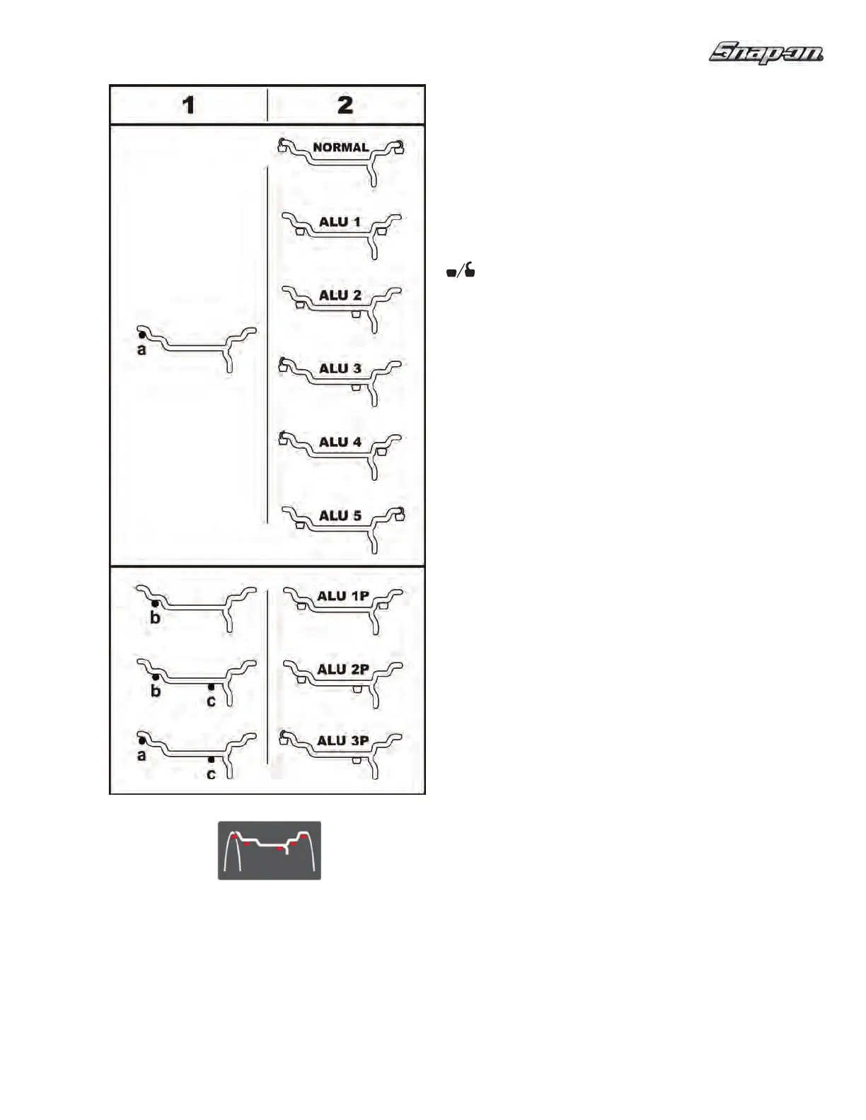
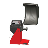
4.3.2 SAPE ARM POSITIONS FOR ALU
WEIGHTS PLACEMENT
Fig.
18 shows the corrected reading positions of the
SAPE arm (1), depending on the required weight
positions (2); adhesive weights and clip-on weights.
Weight Placement illuminated indicators indicate the
weights placement positions on the rim.
— = SAPE arm application point (1).
= resulting in weight position (2).
Normal Tou
ch the SAPE arm to the rim flange (a).
Manually input the rim width dimension. This
mode require the clip-on weights placement.
Alu 1 Touch the SAPE arm to the rim flange (a).
Manually input the rim width dimension. Press
once the Alu key (9). This mode uses the
standardized adhesive weights placement.
Alu 2 Touch the SAPE arm to the rim flange (a).
Manually input the rim width dimension. Press
twice the Alu key (9). This mode uses the
standardized adhesive weights placement.
Alu 3 Touch the SAPE arm to the rim flange (a).
Manually input the rim width dimension. Press
three times the Alu key (9). This mode uses the
standardized weights placement
.
Alu 4
Touch the SAPE arm to the rim flange (a).
Manually input the rim width dimension. Press
six times on the Alu key (9). This mode uses the
standardized weights placement.
Alu 5 Touch the SAPE arm to the rim flange (a).
Manually input the rim
width dimension. Press
seven times on the Alu key (9). This mode uses
the standardized weights placement.
Alu 1P Touch the SAPE arm to the rim ! ange (b). Press
once the Easy Alu Toggle key (9).
Manually input the rim width dimension.
- The internal correction plane for adhesive
weights is precisely indicated by the machine.
Note: Make sure all entries are completed prior to
balancing spin.
Alu 2P Perform the SAPE arm detection in (b-c) points.
- The adhesive weights are placed where the
readings are taken, according to the reading
positions.
Alu 3P Perform the SAPE arm detection in (a-c) points.
- The adhesive weight is placed where the
reading is taken, according to the reading
position.
Note: The Easy Alu Toggle key (6), can retrieve an
alternative ALU P mode.
9
Figure 18