7
ASSEMBLING THE UNIT
Position the welding machine so as to allow the free circulation
of air inside and, as much as possible, prevent metal or other
dusts from penetrating.
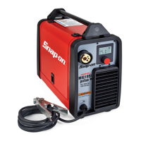
• Electrical supply: ensure that there is a 208 or 230 volt,
single phase, 30 ampere electrical supply within easy reach
of the unit. The input cable supplied is 9 feet long.
Attach a suitable plug making sure the green yellow wire is
attached to the ground terminal of the wall plug. All wiring
should be performed by a qualied electrician
• The machine must be installed by professional personnel.
• All the connections must be performed in compliance
with applicable standards (IEC/CEI EN 60974-9) and with
accident-prevention laws.
• Make sure the power supply voltage corresponds to the
welding machine rating.
• The protection fuses must be sized according to the details
shown on the technical data plate.
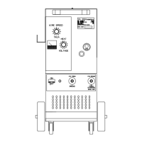
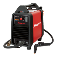
Make sure the ground wire
D
, inside the reel
compartment, is connected to the negative pole
coming out of the dividing wall.
Alongside the two terminals is positioned a plate, which
explains the correct polarity to be used with cored wire
without gaseous protection or a wire with gaseous
protection.
Connect the ground lead clamp
D
to the piece to be welded.
Open the side door. Install the wire reel according to the
instructions provided below.
NOTE: The wire feed motor is inoperative if hinged
side panel is open
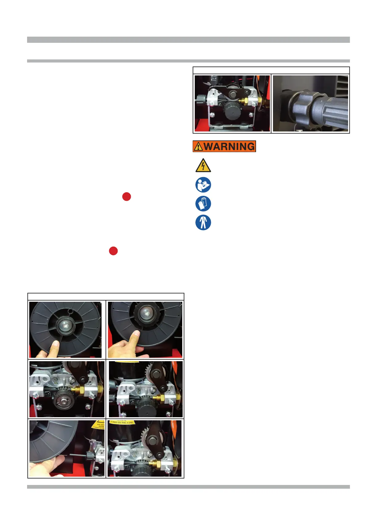
REEL FITTING SEQUENCE
fig.1
fig.2
fig.3 fig.4
fig.5
fig.6
REEL FITTING SEQUENCE
fig.7 fig.8
Electrical shock can result when contacting live
electrode or internal components
Electrical shock can result from absence of
grounding lug.
Welding machine must be connected to
power source in accordance with applicable
electrical codes.
Please refer to the troubleshooting tip sec-
tion located at our web site (www.800AB-
CWELD.com) for information on wiring the
230 V plug if needed.
Do not touch electrode or internal compo-
nents without protection.
Disconnect power before servicing.
Do not remove the grounding lug in any elec-
trical plug.
Electrical shock can cause injury.
During wire installation, the welder must be switched
off and unplugged to prevent the motor roller from
movingpresenting a risk for the operator.
• Fit the reel on the support inside the compartment as
shown in g. 1.
• The reel must be tted on the support so the wire
unwinds in an clockwise direction. It is important for
the wire to be stopped on the reel on the visible side,
see g. 2. Block the reel on the support, as shown in
the illustration.
• Make sure the drive roller is correctly positioned
according to the diameter and type of wire used. To
remove the roller, align the at part of the roller-bearing
pin at the bottom, so the key can be tted inside the
retention screw. Loosen the screw, remove the roller, t
the roller back on so the race corresponds to the wire
used, see gures 3 and 4.
• Cut the wire with a well-sharpened tool, keeping it
between your ngers so that it cannot unwind, insert it
inside the plastic pipe exiting from the gear motor and,
with the aid of a nger, also insert it inside the brass
adapter, see gures 5-6-7-8.
 Loading...