29
1. Warm engine by running for a few minutes. (Refer to the
engine operator’s manual for oil and filter replacement
instructions.)
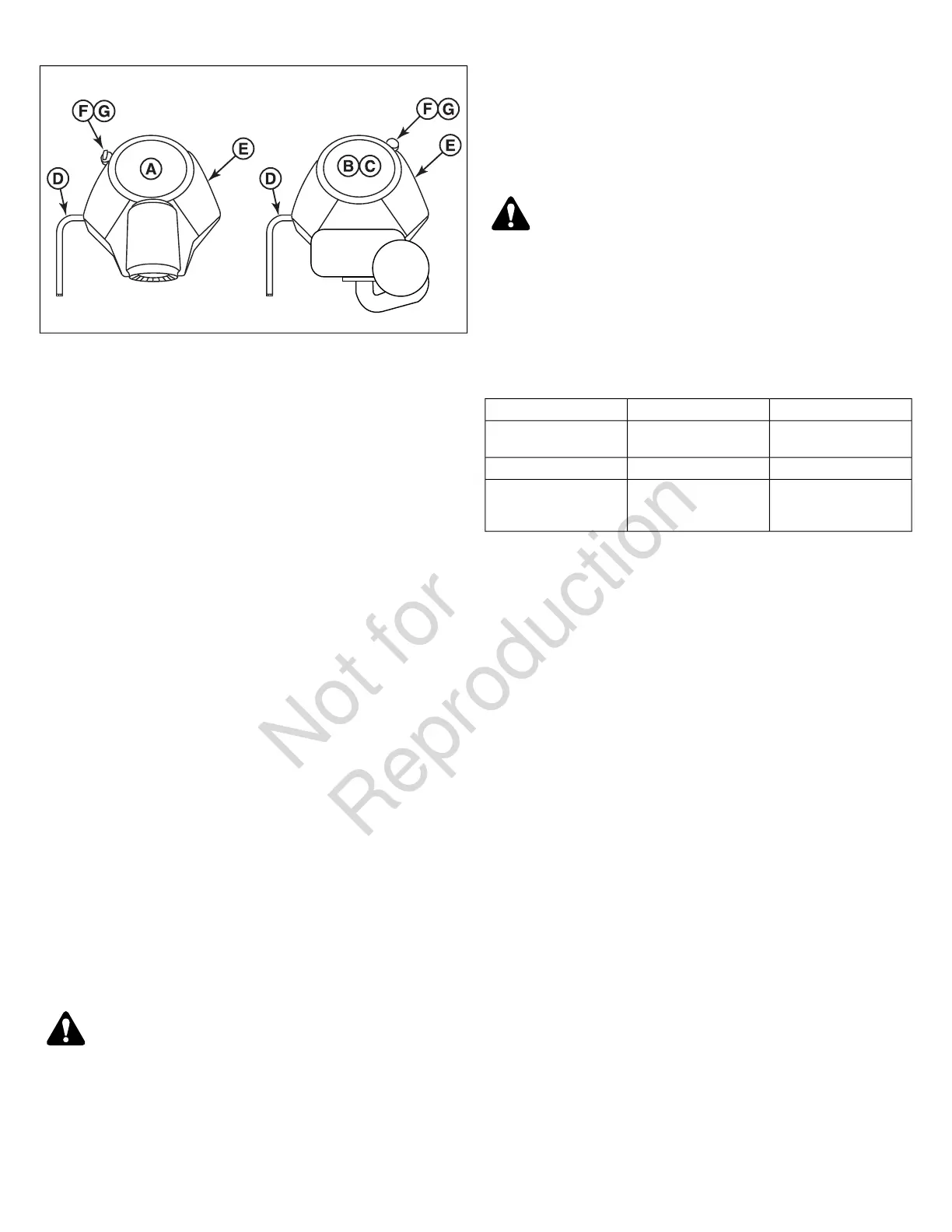
2. Remove the oil drain hose (D) from its storage position and
route the hose so that when the oil drain cap is removed
the oil can be drained into a small pan.
3. Place a small pan under the oil drain hose to catch the oil.
Using the appropriate tools, remove the oil drain cap from
the oil drain hose and drain the engine oil.
4. After draining, replace the cap and wipe up any spilled oil.
Reinstall the oil drain hose to its storage position so it is
retained during normal operation.
5. Place an absorbent shop cloth under the engine oil filter
(E). Remove the engine oil filter and replace with a new
one.
6. Add engine oil (refer to engine operator’s manual) in the fill
tube (F) and check the amount of oil in the engine using
the engine oil dipstick (G).
7. Remove the shop cloth and wipe up any spilled oil.
Engine Maintenance
For engine maintenance schedules and procedures, please
refer to the engine operator's manual.
Electronic Fuel Injection (EFI) System - EFI
Models
EFI is an electronically-controlled fuel management system
which is monitored by an Electronic Control Unit (ECU). A
Malfunction Indicator Lamp (M.I.L.) will illuminate if problems
or faults are detected. Servicing by an authorized dealer is
necessary.
CAUTION
Do not disconnect or reconnect ECU wiring harness connector
or any individual components with the ignition switch in the
"ON" position. This can send a damaging voltage spike
through the ECU.
Unplug harness from ECU before performing any welding on
equipment.
Inspect Muffler and Spark Arrester
Inspect the muffler for cracks, corrosion, or other damage.
Remove the spark arrester, if equipped, and inspect for damage
or carbon blockage. If replacement parts are required, make
sure to use only original equipment replacement parts.
WARNING
Replacement parts must be the same and installed in the
same position as the original parts or fire could result.
Fuse Location and Identification
The electrical system for this unit is equipped with two
replaceable fuses. See the chart below for the circuit, amperage,
and approximate location of the fuses.
Approximate LocationAmperageCircuit
Instrument control panel.20 ampMain (Model 5901280
only)
Instrument control panel.25 ampMain (All other models)
Behind the seat on the
left hand side of the
machine.
15 ampPTO Clutch
Check / Fill Transmission Oil Level
This unit is equipped with two transmission oil tanks. One
transmission oil tank only supplies oil to one transmission. The
level of oil in both transmission tanks must be checked, and if
necessary, filled.
Oil Type: SAE 20W-50 motor oil
1. Locate the transmission oil tanks (A, Figures 30 & 31). The
transmission oil tanks are located on either side of the
engine behind the seat of the unit.
Models with Remote Oil Tanks:
28 snapperpro.com