Deck Lift Assist Springs
Some models are equipped with deck lift assist springs (A,
Figure 66) that assist the operator in raising the mower deck
with the deck lift pedal. The deck lift assist springs are factory
set to provide optimal lifting performance.
66
Although it is fastened with a multi-position anchor, this is not
an adjustment point.
Do NOT attempt to adjust the spring length or lifting performance
will be compromised.
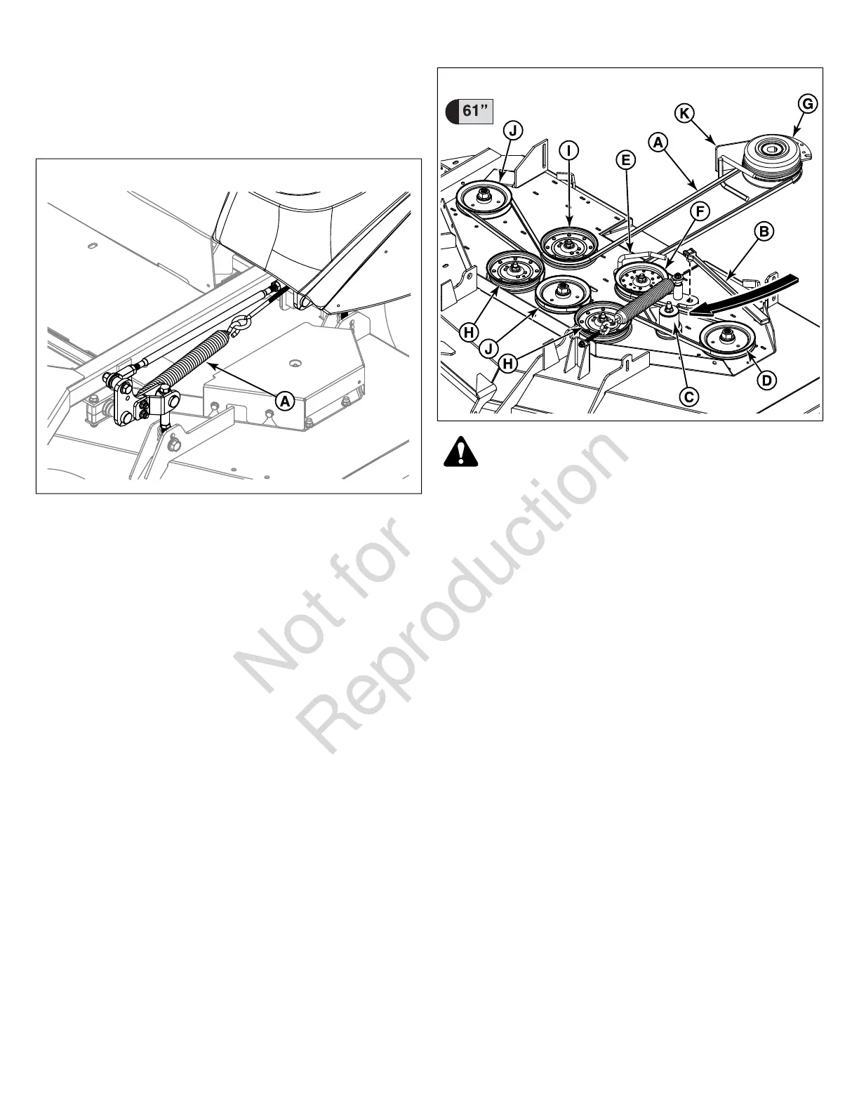
Mower Deck Drive Belt Replacement
(Single Belt Models)
NOTICE
To avoid damaging belts, do not pry over pulleys.
1. Park the unit on a smooth level surface such as a concrete
floor. Disengage the PTO, engage the parking brake, turn
off the engine and remove the ignition key.
2. Lower the mower deck to it's lowest cutting position and
remove the mower deck guards and floor pan to gain access
to the mower deck drive belt (A, Figure 67).
67
WARNING
Use extreme caution when rotating the idler arm with the
breaker bar, due to the increased tension in the spring as the
idler arm is being rotated. Injury may result if the breaker bar
is prematurely released while the spring is under tension.
3. Using a 1/2" breaker bar (B) place the square end in the
opening in the idler arm (C) and rotate the idler arm
clockwise, which will relieve tension on the belt exerted
from the idler arm. Remove the belt from the left hand side
spindle pulley (D). Carefully release the tension on the
breaker bar.
4. Pull the length of the belt removed from the left hand spindle
pulley towards the center of the deck and remove the belt
from the belt guide (E) installed on the adjustable idler pulley
(F). To remove the belt from the belt guide, start with the
leg of the belt between the adjustable idler pulley and the
PTO clutch pulley (G) and raise the belt up and out of the
belt guide.
5. Remove the old belt from the PTO clutch pulley, front
stationary idler pulleys (H), rear stationary idler pulley (I),
and the remaining spindle pulleys (J).
6. Install the new belt onto the right hand side and the center
spindle pulleys and the PTO clutch pulley. Make sure that
the V-side of the belt runs in the pulley grooves and that
the belt is correctly routed through the PTO clutch belt guide
(K) and that the back side of the belt contacts the faces of
the front stationary idler pulleys and the rear stationary idler
pulley.
7. Install the belt into the belt guide installed on the adjustable
idler pulley. To install the belt into the belt guide, start with
the leg of the belt between the adjustable idler pulley and
the PTO clutch pulley and lower the belt down and into the
42 snapperpro.com