19
DISENGAGE: Releases the
parking brake.
ENGAGE: Locks the parking
brake.
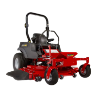
Ground Speed Control Levers: These levers control the
ground speed and direction of the zero-turn riding mower.
The left lever controls the left rear drive wheel and the right
lever controls the right rear drive wheel.
9
Forward Neutral Reverse
The parking brake must be disengaged before attempting to
move the ground speed control levers from the NEUTRAL
position.
Moving a lever forward (A) from the NEUTRAL position (B)
increases the FORWARD speed of the associated wheel, and
pulling back (C) on a lever increases the REVERSE speed.
Moving the levers outwards (D) from the NEUTRAL position
locks the levers in the NEUTRAL LOCKOUT position.
Note:The further a lever is moved away from the neutral
position the faster the drive wheel will turn.
See the Zero-Turn Riding Mower Driving Practice section for
steering instructions.
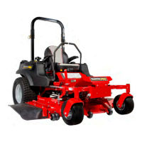
Retractable Seat Belt: The seat belt is used to secure the
operator to the seat.
(Specific to models with a rigid Roll Bar):
The seat belt should always be worn when using this
equipment with a Roll Bar.
(Specific to models with a folding Roll Bar):
The seat belt should always be worn when the Roll Bar is in
the raised position. The seat belt should never be worn when
the Roll Bar is in the down position.
Fuel Tank Cap: To remove the cap, turn counter-clockwise.
Fuel Level Gauge: Displays the fuel level in the
tank.
Seat Adjustment Lever: The seat can be adjusted forward
and back. Move the lever towards the left, position the seat as
desired, and release the lever to lock the seat in position.
Removable Floor Plate: The floor plate can be removed for
easy access to the mower deck. To remove the plate, remove
the retainer hardware and tilt the floor pan up and then
remove from the unit. Reverse the process for re-installation.
Transmission Release Levers:
Symbols Control Name
Transmission Release Levers
Each transmission is equipped with a transmission release
lever. These levers deactivate the transmissions so that the
unit can be pushed by hand. Both transmission release levers
must be in the same position whether you are driving the
unit or pushing it by hand. See Pushing the Unit by Hand for
operational information and control location.
Transmission Oil Fill: Transmission oil is added through the
hydraulic oil tanks. It also serves as extra holding capacity
for oil as the transmissions heat up and the hydraulic oil
expands. See Check / Fill Transmission Oil for oil level check
and fill procedures.
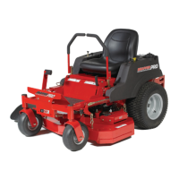
Instrument Control Panel
10
A. Throttle Control