36 SnapperPro.com
4. Slowly release the deck lift foot pedal until it comes to rest
against the stationary pin (E) in the 1-1/2” (3,8 cm) cutting
height hole.
5. Place the cutting height adjustment pin in the storage
hole (F).
To set the cutting height in the range of 1-3/4” (4,4 cm)
and 4-3/4” (12 cm):
1. While sitting in the operator’s seat, press the deck lift foot
pedal forward until it locks into the 5" (12,7 cm) position.
2. Place the cutting height adjustment pin in the desired
cutting height hole.
3. Press the deck lift pedal forward and then push the lock
lever towards the right to release the lock.
4. Slowly release the deck lift foot pedal until it comes to rest
against the cutting height adjustment pin.
To set the cutting height at 5" (12,7 cm):
1. While sitting in the operator’s seat, press the deck lift foot
pedal forward until it locks into the 5" (12,7 cm) position.
2. Place the cutting height adjustment pin in any open
cutting height hole. The lift lock lever holds the mower
deck at 5" (12,7 cm) while cutting.
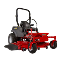
Foot Pedal Adjustment
The deck lift foot pedal can be adjusted to accommodate the
operator’s height for optimal comfort.
To adjust pedal position:
1. Remove the foot pedal (A, Figure 42) from the pedal
mount tab (B).
42
2. Remove the pedal mount hardware (C) and rotate the tab
180 degrees.
3. Reinstall the pedal mount hardware and tighten securely.
4. Reinstall the foot pedal on the pedal mount tab in the
proper orientation as shown in Figure 42.
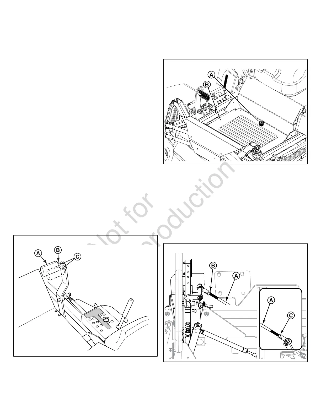
Floor Pan Removal & Installation
This unit is equipped with a removable floor pan which can be
removed to provide better access to the mower deck.
1. Loosen and remove the retaining hardware (A, Figure 43)
that secures the floor pan to the frame of the unit.
43
2. Tilt the back end of the floor pan up and then remove it
from the unit.
3. To re-install the floor pan: Reverse the removal
procedure.
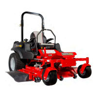
Neutral Adjustment
Each ground speed control lever on this unit is connected to
a transmission by a neutral linkage rod (A, Figure 44). The
neutral adjustment for this machine is achieved by changing
the length of the neutral linkage rods.
44
Determining if Adjustment is Necessary: If the tractor
"creeps" while the ground speed control levers are in the
NEUTRAL LOCKOUT position and the parking brake is
disengaged, then it is necessary to adjust the neutral linkage
rods.