42 SnapperPro.com
Check / Adjust the Mower Deck Drive Belt
Tensioning Spring Length
Mower Deck Drive Belt Tensioning Spring Length
Deck Size Measurement
52" 12" (30,5 cm)
61" 12" (30,5 cm)
1. Set the mower deck to the 3-1/2" (8.9 cm) cutting height.
2. Use the Mower Deck Drive Belt Tensioning Spring Length
chart to determine the correct spring length for your unit.
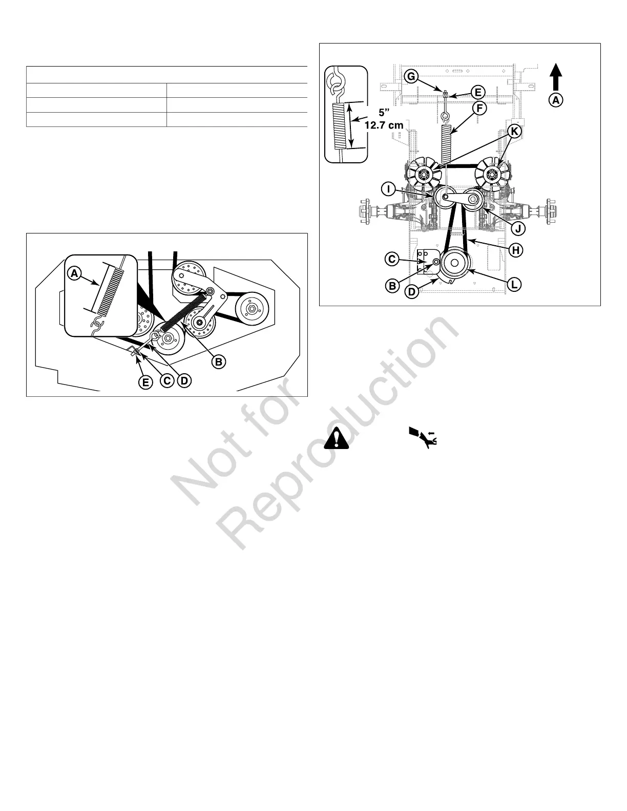
3. Measure the coil length (A, Figure 56) of the mower belt
idler tensioning spring (B). The measurement should
equal the measurement as indicated in the chart. If not,
continue with step #4..
56
4. Loosen the jam nut (C) on the eyebolt (D).
5. Turn the adjustment nut (E) until the measurement as
indicated in the chart is achieved.
6. Re-tighten the jam nut.
7. Re-install the mower deck guards and the floor pan.
8. Run the mower under no-load condition for about five (5)
minutes to break in the new belt.
Transmission Drive Belt Replacement
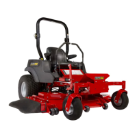
The illustration depicts the transmission drive belt setup as
seen from the top side of the unit and the arrow (A, Figure 57)
indicates the front of the unit.
57
1. Park the mower on a smooth, level surface such as a
concrete floor. Disengage the PTO, engage the parking
brake, turn off the ignition and remove the key.
2. Remove the mower drive belt. See Mower Deck Drive
Belt Replacement for removal instructions.
3. Remove the hardware (B) that secures the clutch anchor
pad (C) to the PTO clutch (D) and disconnect the wire
harness from the PTO clutch.
WARNING
STORED ENERGY DEVICE: Improper release of the belt
tension spring can result in personal injury. Use extreme
caution when removing the spring.
4. Loosen the jam nut (E) on the spring anchor eye bolt (F).
5. Loosen the adjustment nut (G) on the spring anchor
eye bolt to release the majority of the belt tension. Use
caution to remove the nut to completely remove the
tension.
6. Remove the old belt and replace with a new one (H).
Make sure the V-side of the belt runs in the grooves of
the adjustable idler pulley (I) stationary idler pulley (J),
both transmission pulleys (K) and the crankshaft pulley
(L).
7. Reinstall the spring anchor eye bolt into the spring anchor
tab and loosely fasten the adjustment nut.
8. Tighten the nut until the spring reaches a coil-to-coil
measurement of 5" (12.7 cm).
9. Tighten the jam nut.
10. Reinstall the clutch anchor pad to the PTO clutch
and secure using the hardware previously removed.
Reconnect wire harness to the PTO clutch.