E
Installthe GroundSpeed/ SteeringControl
Levers
Positioningthe GroundSpeed/ SteeringControlLevers:
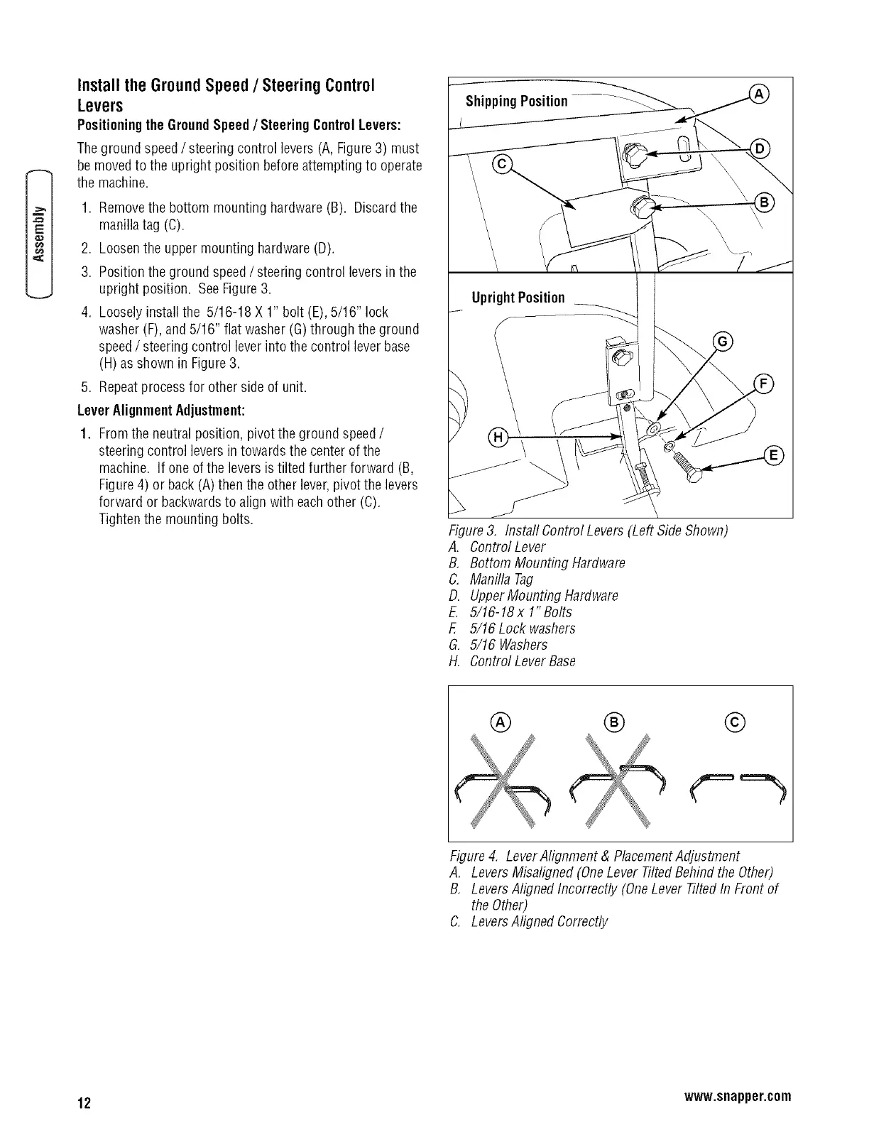
Theground speed/steering control levers (A,Figure 3) must
be moved to the upright position beforeattempting to operate
the machine.
1. Removethe bottom mounting hardware (B). Discardthe
manillatag (C).
2. Loosenthe upper mounting hardware (D).
3. Position the ground speed/ steering control levers in the
upright position. See Figure3.
4. Loosely install the 5/16-18 X 1" bolt (E),5/16" lock
washer (F),and 5/16" flat washer (G) through the ground
speed/ steering control lever into the control lever base
(H)as shown in Figure3.
5. Repeatprocess for other side of unit.
LeverAlignmentAdjustment:
1. Fromthe neutral position, pivot the ground speed/
steering control levers in towards the center of the
machine. If one of the levers is tilted further forward (B,
Figure4) or back (A) then the other lever,pivot the levers
forward or backwardsto align with eachother (C).
Tighten the mounting bolts.
ShippingPosition.......... __../_
Figure3, Instafl Control Levers (Left Side Shown)
A. Control Lever
B, Bottom Mounting Hardware
C. Manilla Tag
D. UpperMounting Hardware
E. 5/16-18x 1"Bolts
F, 5/16 Lock washers
G. 5/16 Washers
H. Control LeverBase
® ® ©
Figure4, LeverAlignment & PlacementAdjustment
A, Levers Misaligned (OneLever TiltedBehind the Other)
B, Levers Aligned Incorrectly (OneLever TiltedIn Front of
theOther)
C. LeversAligned Correctly
12 www.snapper.com