OPERATION
13
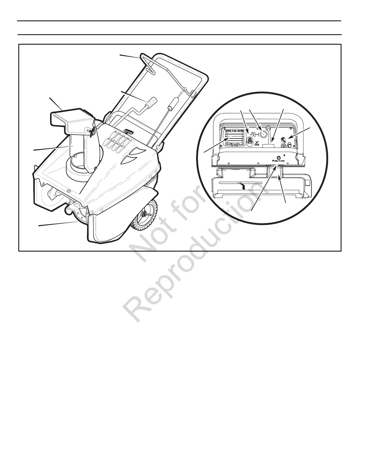
Figure 3
1
2
3
4
6
7
8
9
10
11
12
Control and Equipment Features (Figure 3)
Crank Assembly (1) - Changes the direction of
the discharge chute.
Chute Deflector (2) - Changes the distance the
snow is thrown.
Discharge Chute (3) - Changes the direction the
snow is thrown.
Auger Drive Lever (4) - Starts and stops the auger
which propels the snow thrower.
Auger Blades (5) - Cuts through the snow.
Engine Features (Figure 3)
Stop Switch (6) - If equipped, move to the ON position
to start the engine.
Ignition Key (6) - If equipped, insert and turn to the
ON position to start the engine.
Primer Button (7) - Injects fuel directly into the
carburetor for fast starts in cold weather.
Engine Start Button (8) - On electric start models,
used to start the engine.
Switch Box (9) - On electric start models, used to
attach electrical power cord.
Recoil Starter Handle (10) - Used to manually
start the engine.
Choke Control (11) - Used to start a cold engine.
Spark Plug Access Panel (12) - Remove to access
the spark plug.
5