EasyManua.ls Logo

Snapper VI80 - Page 8

Snapper VI80
40 pages
To Next Page IconTo Next Page
To Previous Page IconTo Previous Page
Loading...
3.
N
EVER
PLACE
MOWER
ON
ITS
LEFT
HAND
SIDE
WITH
SPARK
PLUG
POINTED
DOWNWARD
AS
THIS
WILL
ALLOW
THE
ENGINE
OIL
TO
RUN
OUT
THROUGH
THE
VALVE
TAPPET
VENT.
If
left
too
long,
oil
could
also
leak
past
the
piston
into
the
cylinder.
LUBRICATION:
1.
Change
oil
as
specified
in
the
engine
manual.
2.
Occasionally
put
a
few
drops
of
oil
on
all
movable
parts.
3.
The
ball
bearing
wheels
have
been
factory
greased
and
should
not
be
greased
unless
removed.
4.
Transmission
assembly
is
pre-lubricatod
with
4
ounces
of
Snapper
"OO"
Grease,
Part
No.
1-1050.
To
check
grease,
remove
plug,
Item
No.
4,
and
see
if
grease
is
on
input
gear
assembly.
Item
No.
17.
If
not,
then
add
grease
to
transmission,
and
replace
the
plug.
The
grease
should
be
checked
every
10
hours
of
operation.
ADJUSTING
CUTTING
HEIGHT:
1
.
This
mower
has
solid
through
axles,
front
and
rear,
to
give
superior
strength
and
wheel
alignment.
Thus
with
the
through
axle
design,
it
is
necessary
to
walk
the
height
latches
one
notch
at
a
time
when
it
is
de¬
sired
to
change
cutting
height.
NEVER
UNLATCH
BOTH
SIDES
AT
THE
SAME
TIME.
2.
When
changing
cutting
heights,
make
sure
that
all
latches
are
in
matching
slots.
This
results
in
the
cutting
blade
being
slightly
high¬
er
in
the
rear
to
eliminate
drag.
REFER
TO
PICTURES
BELOW
FOR
PROPER
INSTALLATION
OF
GRASS
CATCHER
AND
SIDE
CHUTE
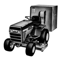
FIGURE
1
FIGURE
2
OPERATING
TIPS
1.
For
forward
speed,
shift
speed
lever.
Item
No.
27,
to
slow
speed
and
press
in
on
clutch
lever.
Item
No.
21.
Desired
speed
then
may
be
obtained
by
shifting
speed
lever.
To
stop
forward
motion
of
machine,
release
dutch
lever
handle,
Item
No.
21,
and
shift
speed
lever
to
neutral.
2.
SNAPPER
V210P
will
cut
either
forward
or
backward.
However,.due
to
the
set
of
the
blade,
slightly
less
power
is
required
for
forward
cutting
than
for
reverse
cutting.
3.
To
turn
at
end
of
row,
push
down
on
handle
bars
to
raise
front
wheels
off
of
the
lawn.
This
permits
turning
on
the
back
wheels
only
and
saves
scuffing
the
lawn.
4.
For
cutting
on
slopes,
it
is
usually
best
to
move
side
to
side
only
—
not
up
and
down
hill.
5.
When
vacuuming
a
paved
walk
or
driveway,
first
lower
deck
to
lowest
position.
It
is
then
best
to
run
V210P
forward
along
the
extreme
left
hand
side
of
the
area
to
be
cleaned.
This
will
pick
up
some
litter
and
windrow
some
litter
to
the
right
of
the
first
swath.
6
.
To
prolong
the
life
and
â– 
usefulness
of
your
mower,
it
is
a
good
practice
to
wash
out
all
the
grass
that
may
be
sticking
to
the
underside
of
the
deck.
No.
1
.
2
.
3.
4.
5.
7.
8.
9
.
10
.
11.
12
.
13.
Part
No.
1-1117
9-0303
3-
1734
1-
1133
5-0243
2-
1
131
1-
0410
9-0042
4-
7714
5-
0262
2-
1
1
30
1-1201
1-1079
1-0936
1-1724
Description
Belt
1/4-28
Hex
Lock
Nut
Transmission
Bracket
Plug
Long
Axle
Assembly
Long
Axle
3/16
x
1-1/8
Roll
Pin
•1/8
x
3/4
Cotter
Pin
Guard
Structure
Short
Axle
Assembly
Short
Axle
5/16-24
Hex
Lock
Nut
Spring
Washer
Polly
"V"
Pulley
Spring
Washor
TRANSMISSION
ASSEMBLY
5-0633
FIGURE
3
No.
Part
No.
Description
Oty.
14.
2-0938
Thrust
Washer
2
15.
1-0172
3/16x1-3/8
Roll
Pin
2
16.
1-1767
Ball
Bearing
1
17.
5-0305
Input
Gear
Assembly
1
18.
1-1179
Seal
2
19.
1-0919
46
Tooth
Gear
2
20.
1-0826
Roll
Pin
2
21.
2-1132
Shaft
1
5-0268
Inboard
Housing
Assembly
1
22.
1-8048
Inboard
Housing
1
23.
1-0932
Bearing
2
24.
1-1110
Shaft
2
25.
2-1115
12
Tooth
Gear
2
26.
2-1116
Differential
Geer
Axle
2
27.
1-1774
Gasket
1
5-0269
Outboard
Housing
Assembly
1
28.
1-8050
Outboard
Housing
1
29.
9-0487
1
4-28x3-1/4
HNCS
4
30.
1-1884
Bell
Crank
Spring
1
31.
5-7087
Belt
Guard
Assembly
1
32.
1-2071
Thrust
Washor
1
33.
1-2047
Bushing
1
34.
1-0816
Thrust
Washer
1
35.
1-1887
3L
250
Engine
Belt
1
36.
3-1013
Tire
Plate
1
37.
1-0927
Driven
Ring
1
38.
5-0630
Driven
Disc
Assembly
1
39.
1-1119
Cover
1
40.
3-0629
Bearing
Holder
Assembly
1
41.
9-0460
7/16-20
Hex
Nut
1
42.
9-0289
3/8-24
Hex
Lock
Nut
1
43.
2-1709
Poly
"V"
Pulley
1
44.
5-0687
Belt
Guard
Assembly
1
45.
2-1708
Hex
Shaft
1
46.
9-0307
10-24
x
1/2
SEMS
5
47.
9-0303
1/4-28
Hex
Lock
Nut
3
48.
1-1880
Clutch
Rod
1
49.
9-0361
5/16*18x5/8
SEMS
4
50.
5-0634
Drive
Disc
Assembly
1
31.
9-0122
3/8
SAE
Washer
1
52.
1-1032
Felt
Seat
1
33.
3-1132
Bearing
Shield
1
54.
3-9562
Deck
Bracket
1
53.
9-0390
3/8
Internal
Tooth
L'-Washer
2
56.
9-0155
3/8-24
Hex
Nut
3
57.
1-0948
Idler
Pulley
1
58.
1-1877
Bell
Crank
1
59.
1-0947
idler
Spring
1
60.
9-0174
3/8-24
x
3
HHCS
1
61.
3-1006
Idler
1
62.
9-0107
1/4-28
x
1-1/4
HHCS
1
63.
1-1873
Shifter
Cone
1

Related product manuals