© Trynex International 2009 L1040
7 — 28
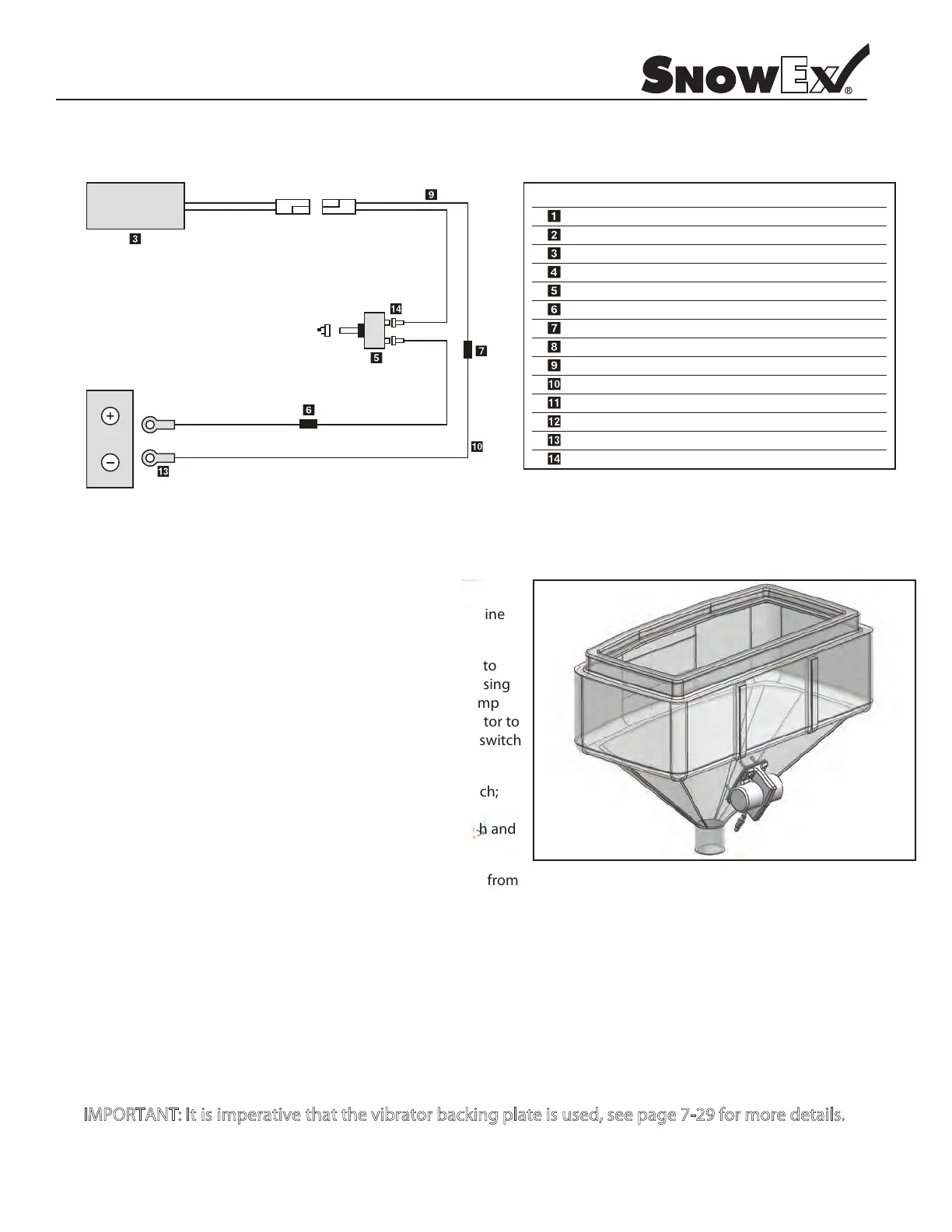
Wiring Diagram and Instructions
Model # VBR-080
.ytQ noitpircseD .oN traP yeK
4
4
tuN kcoL ''8/3
4214 D
D 6160 3/8'' - 16x2 Hex Bolt
4
4
1
2
1
1
1
1
1
1
1
1
2
rotarbiV 08-CD 1616 D
D 6579 Vibrator Backing Plate
hctiwS ffO/nO 4816 D
esuF pmA 01 3326 D
D 6234 Butt Connector
D 6344 Dielectric Grease
D 6403 20' Universal Harness
D 6404 10' Battery Harness
D 6406 Rubber Switch Boot
redloH esuF 5246 D
lanimreT gniR 5017 D
D 7106 Spade Connector
(+) Pos.Red
(–) Neg. Black
(–) Neg. Black
(+) Pos.Red
12 VOLT
BATTERY
Wiring Installation and Instructions
Step 1: First, install switch at desired location. This will determine
what the proper wire length should be.
Step 2: Run spreader/vehicle harness from the rear of vehicle to
switch area. Remove approx. 3'' of the black outer jacket exposing
two single leads (red and black), strip a 1/4'' o each lead. Crimp
1/4'' female connector on red lead and crimp the butt connector to
the black lead. Place the female spade/red wire to the on/o switch
and leave the black wire for the next step.
Step 3: Route the power harness from the battery to the switch;
this will determine proper length to cut wires. Repeat step #2
regarding cable jacketing and connection points to the switch and
butt connector.
Step 4: Install an inline 10 amp. fuse on the positive (red) lead from
the battery to the switch. Locate an easily accessible place, out of
the elements, for the fuse and remove approx. 3'' of the black outer jacket exposing two single leads (red and black). Cut the
red lead in half and strip a 1/4'' o each lead. Insert into the fuse connector and crimp. Insert 10 amp. blade fuse into connector.
Step 5: At the battery end of the power harness, remove 8'' of the black outer jacket exposing two single leads (red and black).
Strip 1/4” o each lead. Crimp a 3/8'' lug terminal to each lead and attach the red lead to the positive side of the battery and the
black lead to the negative side of the battery.
Step 6: Locate vibrator approx. 6" to 8" from the top of throat entry and drill four 3/8" holes in rear hopper face. Bolt the vibrator
in place using bolts provided, with backing plate inside the hopper.
I PORTANT I i i e a i e t e i backi p te i u e , ee ag 7 29 e ai
575 Hopper Shown