V
.
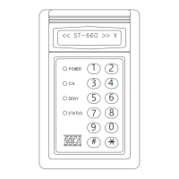
INSTALLATION OF PROXIMITY READER :
1. Reader connections :
ST-660 Wiring diagram
*
Open door relay contact rating DC12V 2A or AC120V 1A
*
Tamper switch contact rating DC24V / 0.5A
P. 12
Anti-
Tamper switch, normally open contact
8 PIN
CONNECTOR
6 PIN
CONNECTOR
Exit push button
Door control relay. Dry contact ( N. C. )
GND
DC +12V
Anti-Damage alarm output
Anti-
Tamper switch, normally close contact
Anti-Tamper switch, common contact
GND
Door detection sensor point 2
Door detection sensor point 1
Anti-Duress alarm output
Orange
Red
Brown
Black
Purple
BLUE
Green
Yellow
Yellow
Purple
Blue
Green
Brown
Red
Door control relay. Dry contact ( N. O. )
Door control relay. Dry contact ( COM. )