4 SOCOMEC - Réf.: 678 623 G GB
INTRODUCTION
GENERAL INTRODUCTION
NEW ATI enclosure integrates a new
4-pole changeover switch including
electronic’s control to meet standard
IEC 60947-6-1. Thanks to the chan-
geover switch technology, it is always
possible to manually operate the sys-
tem to guarantee the changeover panel
operation in any situation.
The new enclosure design allows
switch front panel access to:
• Avoid opening of the enclosure for
manual operation
• Allow electronic module access for
programming and monitoring
• Simplify connections between the
mechanical switch and the electronic
module.
With the mode switch in manual posi-
tion, Padlocking, as well as handle
insertion operations are then directly
accessible from the front panel.
The electronic module, also accessible
from the front panel, includes:
• Sources monitoring
• Metering display (V and f as standard)
• Test operations and Sequences pro-
gramming using keypad.
• ATI 1000 A
• ATI 1250 A
• ATI 1600 A
New ATI range models
MODEL
• ATI 250 A
• ATI 400 A
• ATI 630 A
• ATI 800 A
ATI TRANSFER PANEL RANGE
The new ATI panel range will be available from 250 A to 1600 A.
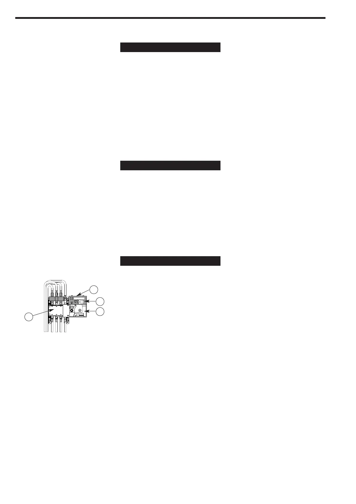
1. A mechanical switch.
2. A motorized block to operate the switch electrically.
3. An electronic module on the top of the motorized block, driving loss of mains
and main’s return sequence.
4. A reset button.
NEW MOTORIZED CHANGEOVER SWITCH
The new switch included in the enclosure is made of 3 different parts:
Standard offer includes Bottom cable entry. Top cable entry is offered as an
option.
Features and benefits:
• The new Motorisation block is inclu-
ded in a moulded case
• It is possible to remove the motorized
block and the electronic module
without being obliged to disconnect
the power cables
• Manual operation directly acts on the
shaft of the mechanical switch for
better reliability
• The complete enclosure meets stan-
dard IEC 60947-6-1 (ATS applications)
• The enclosure is self-powered (from
Main and Gen sources). There is no
need for an external power source to
allow automatic sequence after loss
of power
• All thresholds and timers can be set
using the display and the keypad, or
via modbus (optional)
• The standard product integrates
voltage and frequency control for
better diagnostic
• Main sensing circuit is 3 phases and
Gen sensing circuit is single phase
• Standard product includes, phase to
phase + phase to neutral voltage
measurement and displays system
frequency (phase 1) and switch num-
ber of operations.
• The product including metering allows
current measurement as well as power
metering (kW, kVar, kVA and PF).
1
2
3
4
ATI 035 A
 Loading...