13
EN
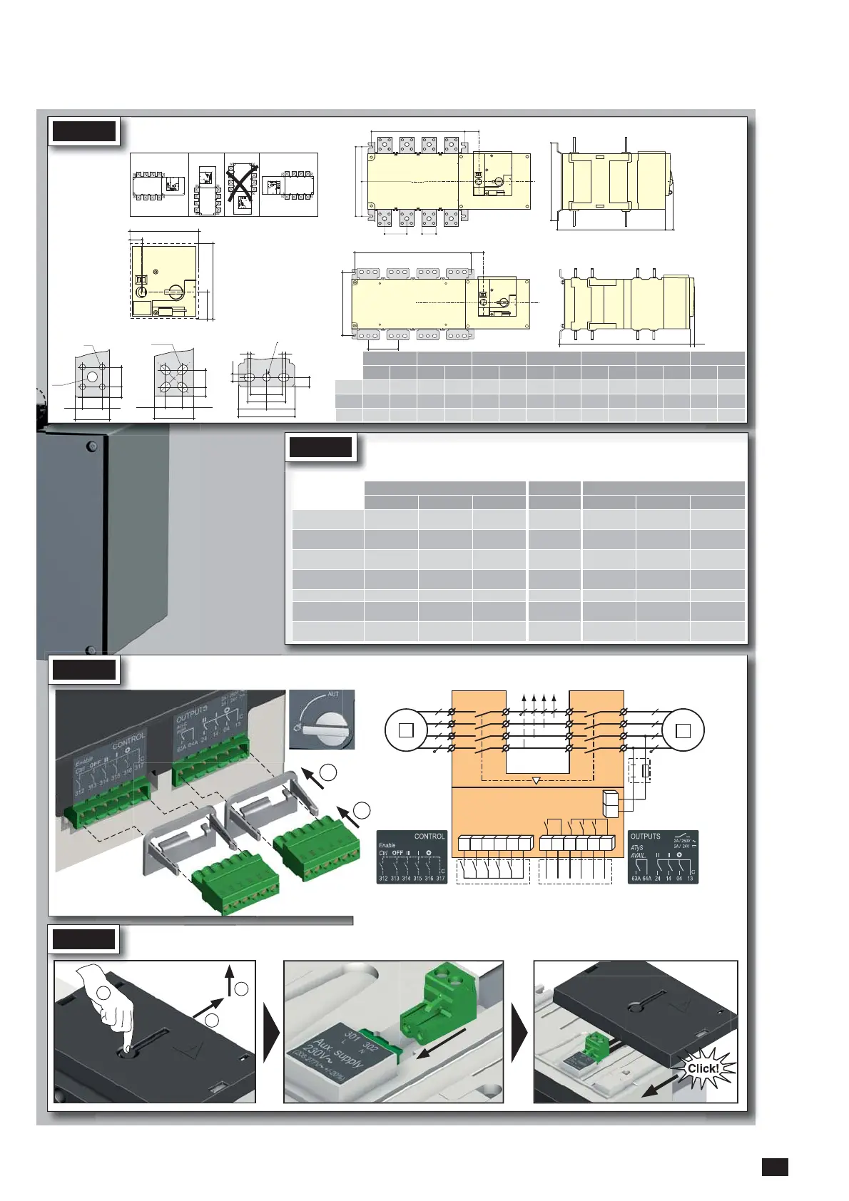
CONTROL / COMMAND Terminals - Ensure that the product is in Manual Mode.
STEP 3
1
1
2
301 3022
312 313 314 315 316 317 63A 64A 24 14 04 13
STEP 4
Power Supply Terminal - Remove the Top cover to access and connect the terminal - Replace the cover before putting in service.
1
2
3
2
Connect the product with a cable of section of 1,5 to 2,5 mm
2
.
Screw M3 - Tightening torque: min.: 0.5 Nm - max.: 0.6 Nm
STEP 1
Installation
50.5
20
138
150
ATyS 1250 AATyS 800 to 1000 A
ATyS 800 to 1600 A
ATyS 2000 to 3200 A
ATyS 1600 to 3200 A
33 8.58.5
50
3310
ø 9
ø 15
16 x 11
60
28.5 15.7515.75
28.515
15
5
5
12.5
25
25
30
30
45
45
90
ø12.5
Door cut-out for
front panel.
=
280
=
250
C
M 51,5
TU
21
M
T
250
C21
51.5
Dimensions
in mm.
Attention:
Ensure that the
product is installed on
a flat rigid surface.
Orientation:
Recommended Ok Ok
800 A 1000 A 1250 A 1600 A 2000 A 2500 A 3200 A
3 P 4 P 3 P 4 P 3 P 4 P 3 P 4 P 3 P 4 P 3 P 4 P 3 P 4 P
M 255 335 255 335 255 335 347 467 347 467 347 467 347 467
T 80 80 80 80 80 80 120 120 120 120 120 120 120 120
C 391 391 391 391 391 391 391 391 523 523 523 523 523 523
STEP 2
Power Terminal Connections
To be connected using terminal lugs, rigid or flexable busbars.
FRAME B6 FRAME B7 FRAME B8
800 A 1000 A 1250 A 1600 A 2000 A 2500 A 3200 A
Minimum cable section
Cu (mm
2
) at Ith
2x240 - - - - - -
Minimum cable section
Cu (mm
2
) at Ith
2x50x5 2x60x5 2x80x5 2x100x5
3x100x5 4x100x5 3x100x10
Maximum cable section
Cu (mm
2
)
2x300
4x185 4x185 6x185
---
Maximum Cu busbar
width (mm)
63 63 63 100
100 100 100
Type of screw
M8 M8 M10 M12 M12 M12 M12
Recommended tighten-
ing torque (N.m)
20 20 20 40 40 40 40
Maximum tightening
torque (N.m)
26 26 26 45 45 45 45

 Loading...


