SOCOMEC - Ref. : 875 645 D
5
E NG LI S H
CLIMATIC ENVIRONMENT
T
o guarantee optimum operation, it is
r
ecommended that this device is used
between - 5 to + 45 °C with a relative
humidity of between 20 and 85
%.
Note:
The COUNTIS can be installed on a
DIN EN 50022 rail (DIN 43880).
CONNECTION
The Countis A
Tv2 and A
Tiv2 consist of
connection terminals of 1 to 6 mm
2
for
currents and voltages.
Recommendation:
• Avoid close proximity with systems
generating electromagnetic distur
-
bances
• Avoid vibrations including accelera-
tions of mor
e than 1 G for frequen-
cies lower than 60 Hz.
SAFETY INSTRUCTIONS (U
,
I, F)
To avoid damaging the device, take
care to observe the following before
connecting the device:
• indications on the casing,
• network fr
equency: 50 or 60
Hz,
• maximum permanent voltage at
voltage input terminals of 400 V AC
±
20
%
phase/phase,
• maximum permanent current of 7 A
(connection fr
om curr
ent transfor
-
mer(s)).
Note:
The minimum torque for the fixed
terminal is 0.8 Nm.
Recommendation:
We recommend that the auxiliary
voltage and the voltage inputs should
be protected with 0.5 A fuses or
BS 88 2A gG.
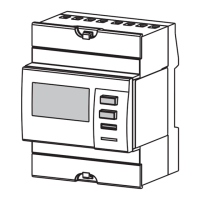
INSTALLATION
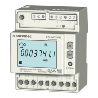
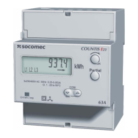
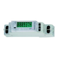
PRESENTATION (continued)
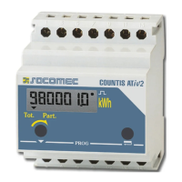
COUNT 119 B
a kWh display
b Total and partial meter display, or scrolling parameter settings
c Displays t1 and t2 rate meters
d Flashing LED consumption indicator (10 Wh/pulse)
e Validation/scrolling of parameter settings
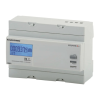
COUNTIS
ATiv2 DOUBLE RATE