34
EN
DIRIS B - 546 770 A - SOCOMEC
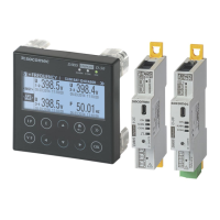
6.3. Connecting the current sensors
6.3.1. Connection concept
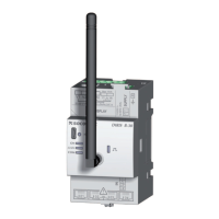
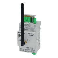
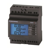
DIRIS B
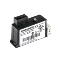
TE / TR / TF current sensors
Recommendations:
4RDNMKX2.".,$"B@AKDRENQSGDBTQQDMSRDMRNQRNQDPTHU@KDMSB@AKDRNESGDENKKNVHMFSXOD1)
RSQ@HFGSSVHRSDCO@HQTMRGHDKCDC5ŰB@S(((¦"HM@BBNQC@MBDVHSG($"$C
- It is recommended that current sensors are installed in the same direction.
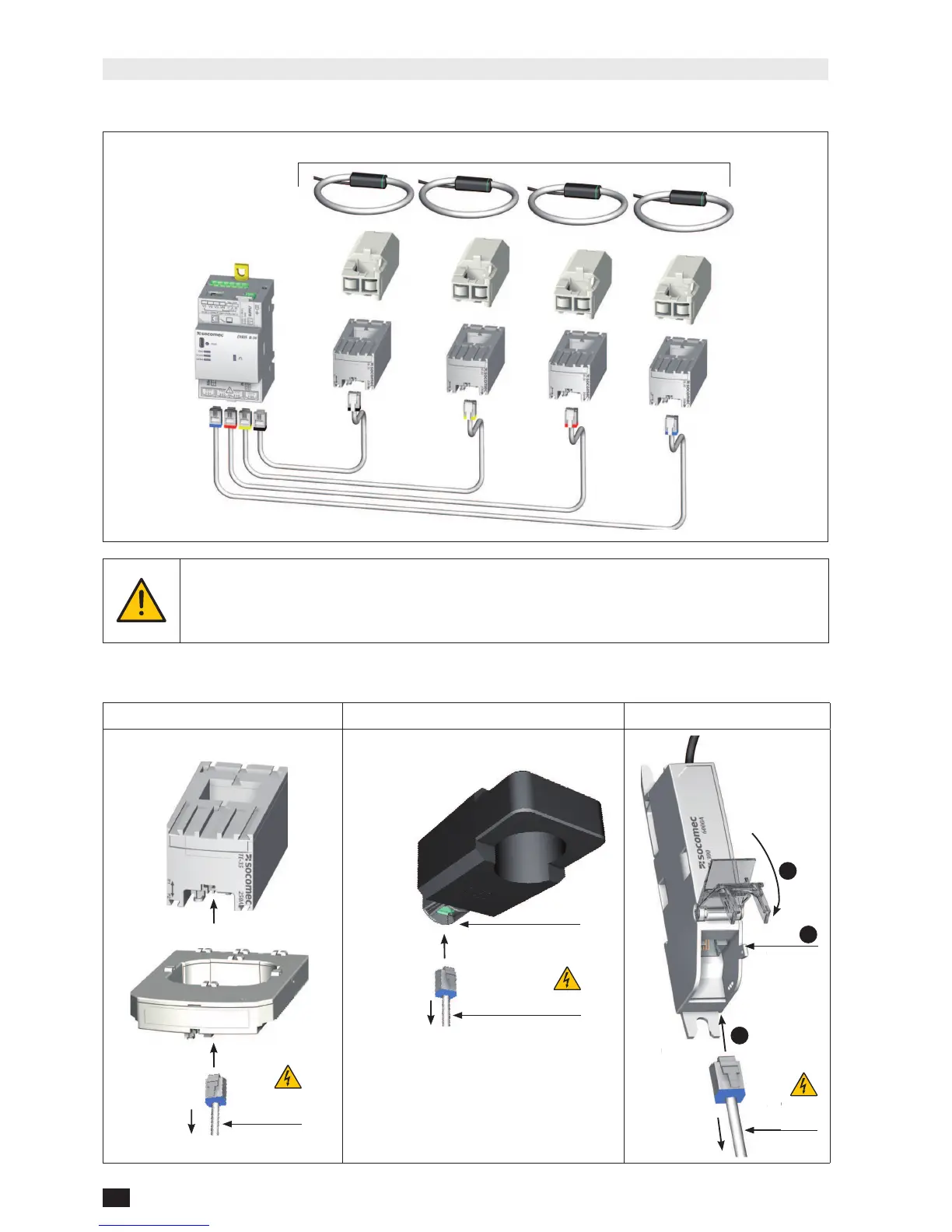
6.3.2. Details of the RJ12 connections for each current sensor
TE TR
TF
SOCOMEC
cable for
current sensors
Click!
PMD
DIRIS B
DIRIS Digiware
TE-18 to TE-55
TE-90
SOCOMEC cable for
current sensors
Do not bring into contact
with dangerous voltages
PMD
DIRIS B
DIRIS Digiware
Click!
SOCOMEC
cable for
current sensors
Cover sealing