EasyManua.ls Logo

socomec DIRIS B-10L User Manual

socomec DIRIS B-10L
76 pages
To Next Page IconTo Next Page
Page #1 background imageLoading...
Page #1 background image
Power Monitoring Device with wireless
LoRaWAN communication
DIRIS B-10L
INSTALLATION AND OPERATING MANUAL
EN

Table of Contents

Question and Answer IconNeed help?

Do you have a question about the socomec DIRIS B-10L and is the answer not in the manual?

socomec DIRIS B-10L Specifications

General IconGeneral
Brandsocomec
ModelDIRIS B-10L
CategoryMeasuring Instruments
LanguageEnglish

Summary

1. Documentation

2. Hazards and Warnings

2.1. Risk of Electrocution, Burns or Explosion

Details risks of electric shock, burns, and explosions during installation and use.

2.2. Risk of Damaging the Device

2.3. Liability

Outlines installer's and manufacturer's responsibilities regarding device installation and use.

3. Preliminary Operations

4. Presentation

4.1. DIRIS B-10L Presentation

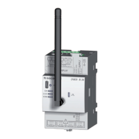
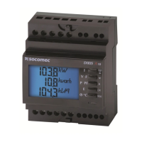
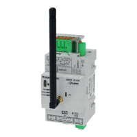
Introduces the DIRIS B-10L as a compact PMD for LoRaWAN communication.

4.1.1. Range

Details the product range, including the device and accessories.

4.1.2. Functions

4.1.3. Dimensions

4.2. Optional Modules Presentation

4.2.1. Range

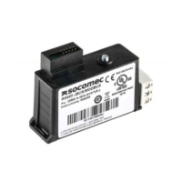
Presents the DIRIS O-iod and DIRIS O-it optional modules.

4.2.2. Dimensions

Displays the dimensions of the optional DIRIS O-iod and O-it modules.

4.3. Presentation of the Remote Antenna

4.4. Presentation of Associated Current Sensors

4.4.1. TE Solid-Core Current Sensors

4.4.1.1. Range

Lists the available models, pitches, and current ranges for TE solid-core sensors.

4.4.1.2. Dimensions

Provides dimensional data for TE solid-core current sensors.

4.4.2. TR Split-Core Current Sensors

4.4.2.1. Range

Lists available TR split-core sensor models and their current ranges.

4.4.2.2. Dimensions

Details the dimensions for TR split-core current sensors.

4.4.3. TF Flexible Current Sensors

4.4.3.1. Range

Covers the range of TF flexible current sensors.

4.4.3.2. Dimensions

Provides dimensional data for TF flexible current sensors.

4.4.4. Adaptor for 5A or 1A Current Transformers

4.4.4.1. Range

Details the range and specifications of the 5A/1A current transformer adaptor.

4.4.4.2. Dimensions

Shows the dimensions of the 5A/1A current transformer adaptor.

5. Mounting

5.1. Recommendations and Safety

Provides safety recommendations and references for mounting procedures.

5.2. DIRIS B-10L Mounting

Describes how to mount the main DIRIS B-10L unit.

5.2.1. DIN Rail Mounting

Instructions for mounting the DIRIS B-10L on a DIN rail.

5.2.2. Plate Mounting

Instructions for mounting the DIRIS B-10L on a plate.

5.2.3. Sealing Accessory for Sensors

5.3. Optional Modules Mounting

5.3.1. Optional Module Mounted on DIRIS B-10L

Step-by-step guide for mounting optional modules onto the DIRIS B-10L.

5.3.2. Mounting an Optional Module on an Optional Module

Details the process of mounting one optional module onto another.

5.4. TE Solid-Core Sensors Mounting

5.4.1. Mounting Accessories

Lists accessories for mounting TE solid-core sensors.

5.4.2. DIN Rail Mounting

Instructions for mounting TE solid-core sensors on a DIN rail.

5.4.3. Plate Mounting

5.4.4. Mounting on a Cable with Clamping Collar

5.4.5. Busbar Mounting

5.4.6. Sensors Assembly

5.4.7. Sealing Accessories for Sensors

5.5. TR/iTR Split-Core Sensors Mounting

5.5.1. Cable Mounting

Details the cable mounting procedure for TR/iTR split-core sensors.

5.6. TF Flexible Sensors Mounting

5.6.1. Cable or Bus Bar-Mounting

Instructions for mounting TF flexible sensors on cables or bus bars.

5.7. Installing the 5A Adaptor

6. Connection

6.1. DIRIS B-10L Connection

Explains the electrical connections for the DIRIS B-10L device.

6.2. Connecting the Optional Modules

6.2.1. Input/Output Modules

Details the connection of DIRIS O-iod and DIRIS O-it optional modules.

6.3. Connecting the Current Sensors

6.3.1. Connection Concept

Outlines the general concept for connecting current sensors to the DIRIS B-10L.

6.3.2. Details of the RJ12 Connections for Each Current Sensor

6.3.3. Connection to the Electrical Network and to the Loads

6.3.3.1. Configurable Loads Based on the Network Type

Summarizes configurable loads based on different network types.

6.3.3.2. Description of the Main Network and Load Combinations

Illustrates main network and load connection combinations.

6.3.4. Connection of the Functional Earth

7. Product LEDs

8. LoRaWAN Communication

8.1. General Information

Provides general information about LoRaWAN communication.

8.2. LoRa Key Recovery

Explains how to recover LoRa keys.

8.3. LoRa Payloads for DIRIS B-10L Measurements

Details the structure of LoRa payloads for measurements.

8.4. LoRaWAN to Ethernet Modbus TCP Gateway

8.5. EU Declaration of Conformity

9. Configuration

9.1. Configuration using Easy Config System

Details how to configure the DIRIS B-10L using the Easy Config System software.

9.1.1. Connection Modes

Describes connection modes for configuration.

9.1.2. Configuring the DIRIS B-10L using Easy Config System

Step-by-step guide to configuring the device via Easy Config System.

9.2. Configuration from the DIRIS D-30 Remote Display

9.2.1. Connection Mode

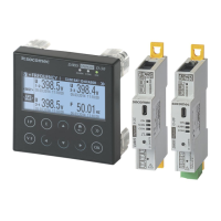
Describes the connection mode for remote display configuration.

10. Alarms

10.1. System Alarms

Details system alarms that can be activated during commissioning.

10.2. Measurement Alarms

Details how to configure measurement alarms based on thresholds.

10.3. Protection Alarms

10.4. Logical Alarms

11. Technical Characteristics

11.1. DIRIS B-10L Characteristics

Comprehensive technical characteristics of the DIRIS B-10L.

11.1.1. Mechanical Characteristics

Details the mechanical features of the DIRIS B-10L.

11.1.2. Electrical Characteristics

Lists the electrical specifications of the DIRIS B-10L.

11.1.3. Input Characteristics

Describes the input characteristics of the DIRIS B-10L.

11.1.4. Measuring Characteristics

11.1.5. Communication Characteristics

11.1.6. Environmental Characteristics

11.1.7. Electromagnetic Compatibility

11.1.8. Safety

11.1.9. Service Life

11.2. DIRIS O Optional Modules Characteristics

11.3. DIRIS D-30 Display Characteristics

11.4. TE, TR /iTR and TF Sensors - Characteristics

12. Performance Classes

12.1. Specification of the Characteristics

Specifies performance classes and measurement ranges according to IEC 61557-12.

12.2. Evaluation of the Power Supply Quality

Related product manuals