SOFAR 3K~6KTLM-G2 User manual
Copyright © Shenzhen SOFARSOLAR Co., Ltd
two live part in the worst-case rated operating condition when used as intended.
WiFi/GPRS/Ethernet interface
4.1. Electrical connection
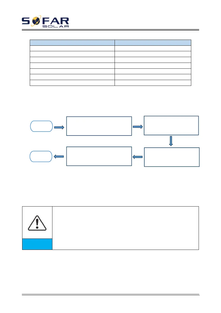
Figure4-1 Shows the flowchart for connecting cables to the inverter.
4.2. Connecting PGND Cables
Connect the inverter to the grounding electrode using protection ground
(PGND) cables for grounding purpose.
The inverter is transformer-less, requires the positive pole and
negative pole of the PV array are NOT grounded. Otherwise it will cause
inverter failure. In the PV power system, all non current carrying metal
parts (such as: PV module frame, PV rack, combiner box enclosure,
inverter enclosure) should be connected to earth.
Prerequisites:
The PGND cables are prepared ( ≥5mm²outdoor power cables are
recommended for grounding purposes),the color of cable should be yellow-green.
Connect AC output
power cable
Connect communication
cables (not mandatory)
 Loading...