HYD 3K~6K-EP User manual
Copyright © Shenzhen SOFARSOLAR Co., Ltd。
4.3. PV Connection
Procedure:
Step 1 Select the appropriate cable type and specifications according to the
table4-3.Remove cable glands from the positive and negative connectors.( It is
recommended that the positive and negative be distinguished by different colors).
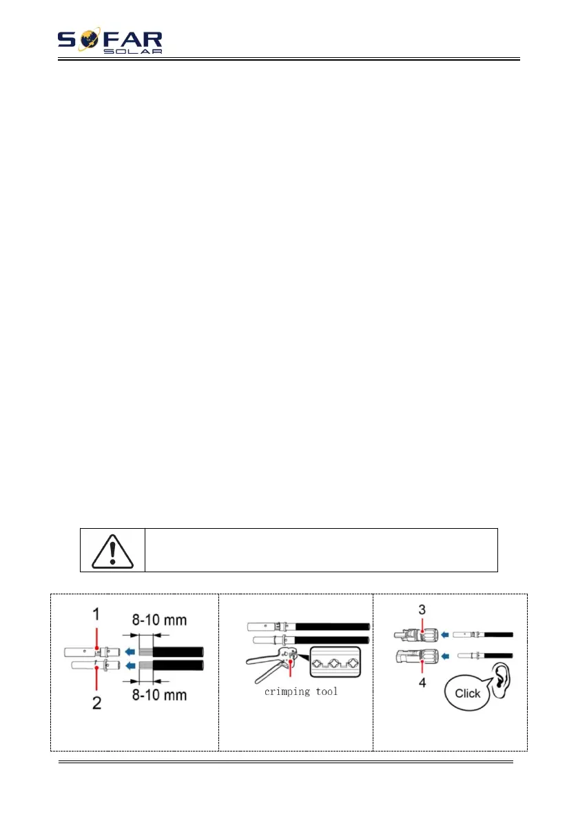
Step 2 Remove the insulation layer with an appropriate length from the
positive and negative power cables by using a wire stripper as show in Fig.①.
Step 3 Insert the stripped positive and negative power cables into the positive
and negative metal terminals respectively and crimp them using a clamping tool.
Ensure that the cables are crimped until they cannot be pulled out by force less than
400 N, as shown in Fig.②③.
Step 4 Insert crimped power cables into corresponding housings until you
hear a "click" sound. The power cables snap into place.
Step 5 Reinstall cable glands on positive and negative connectors and rotate
them against the insulation covers.
Step 6 Insert the positive and negative connectors into corresponding PV
terminals of the inverter until you hear a "click" sound, as shown in Fig.⑥.
To remove the positive and negative connectors from the inverter, insert a
removal wrench into the bayonet and press the wrench with an appropriate strength,
as shown in Fig.⑦.
Before removing the positive and negative connectors, ensure that
the DC SWITCH is OFF.
Fig.4-2 Connect PV
1: Positive metal contact
2: Negative metal contact ①
3: Positive connector
4: Negative connector ③