Context
Cross-Sectional Area (mm)
4.0~6.0
Recommended ValueRange
4.0
External Cable Diameter(mm)
4.5~7.8
DC input connectors are classified into positive and negative connectors, as shown in Figure
4-24 and Figure 4-25.
1. Housing 2. Cable gland 3. Positive connector
1. Housing 2. Cable gland 3. Negative connector
Table 4-6 Recommended DC input cable specifications
Figure 4-23 Positive connector composition
Figure 4-24 Negative connector composition
Positive and negative metal terminals are packed with positive and negative connectors
respectively. Separate the positive from negative metal terminals after unpacking the SOFAR
10-20KTL to avoid confusing the polarities.
Note
All rights reserved Shenzhen SOFARSOLAR Co ., Ltd.
C
37
All rights reserved Shenzhen SOFARSOLAR Co ., Ltd.
C
38
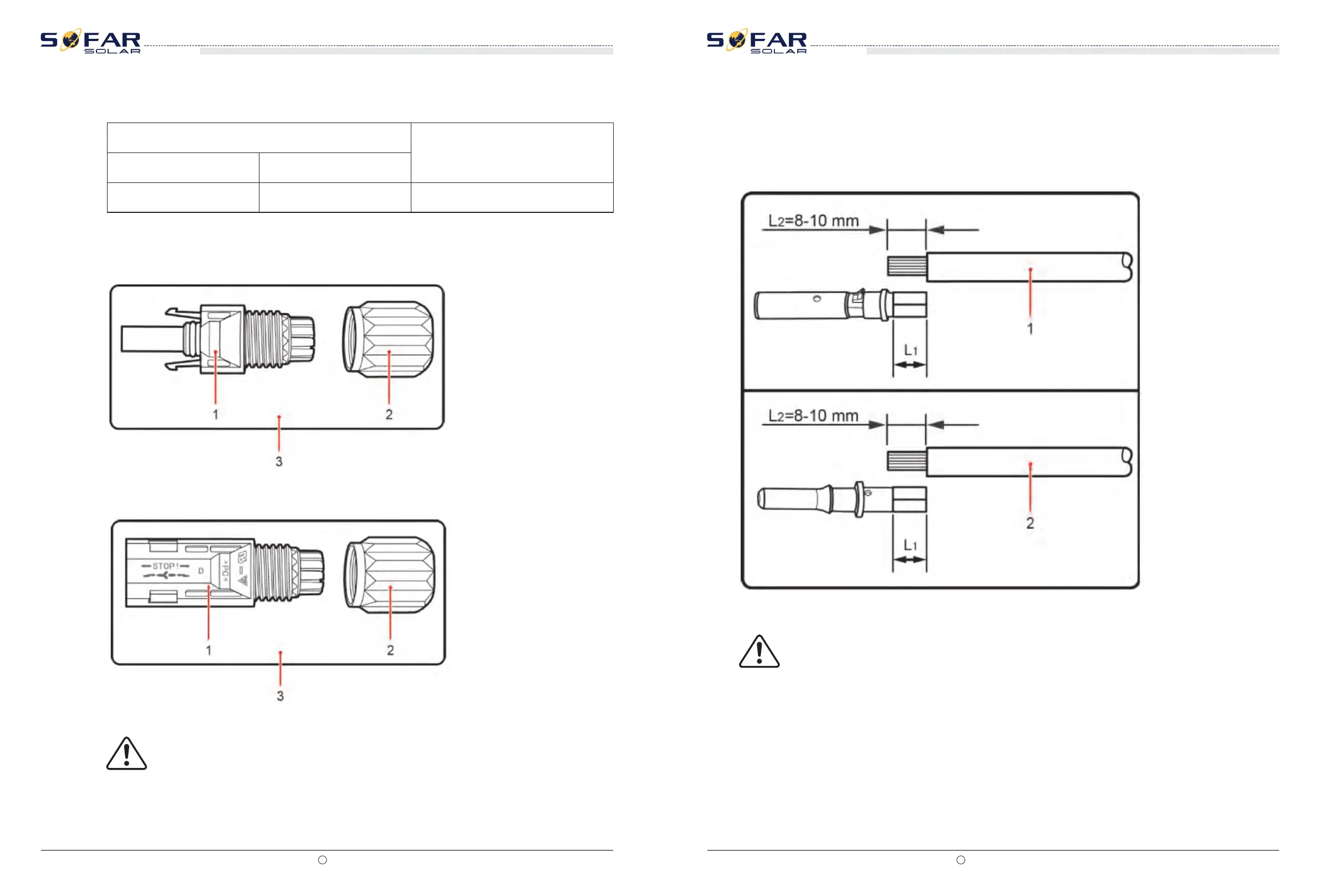
Procedure
Step 1 Remove cable glands from the positive and negative connectors.
Figure 4-25 Connecting DC input power cables
1. Positive power cable 2. Negative power cable
L2 is 2 to 3 mm longer than L1.
Note
Step 2 Remove the insulation layer with an appropriate length from the positive and negative
power cables by using a wire stripper as show in Figure 4-26.
SOFAR 10K~20KTL
User manual
SOFAR 10K~20KTL
User manual