All rights reserved Shenzhen SOFARSOLAR Co ., Ltd.
C
45
All rights reserved Shenzhen SOFARSOLAR Co ., Ltd.
C
46
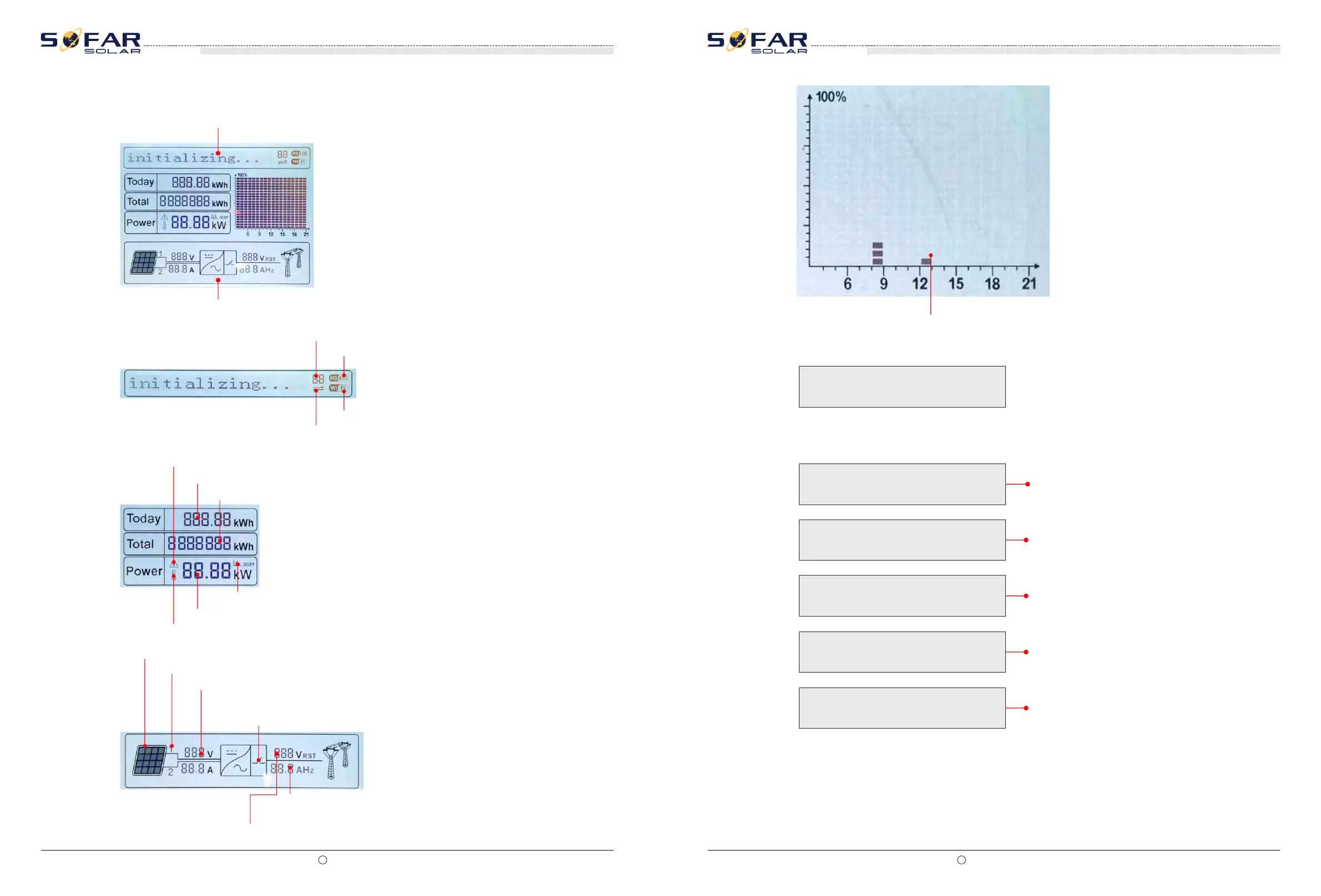
6.2 Standard Interface
LCD standard interface is used to display inverter states、information and parameter setting etc.
LCD displays the updates of inverter energy、power、input information、warning information etc
A1 - Indicates modbus communication address.。
A2 - RS485 communicating
A3 - Light ON for RS485 communicating
A4 - WIFI communicating
A5 - Light flashes to warn over frequency and power derating. Light ON to warn remote
A6 - Indicates today’s energy
A7 - Indicates the total energy
A10 - MPPT SCAN function is activated (not available)
A9 - Indicates real time output power
A8 - Light ON warning for inverter high temperature
A11 - Light ON when input voltage over 350V
A12 - Indicates real time input voltage and current channel
A13 - Indicates the input voltage and current of phase 1&2 and displays in turns in
every three seconds
A14 - Light ON when the state is normal
A16 - Indicates R/T/S phase current or frequency and displays in turns
in every three seconds
A15 - Indicates R/T/S phase voltage and displays in turns in every three seconds
When power-on, LCD interface displays INITIALIZING, refer below picture.
when control board successfully connected with communication board, the LCD display the
current state of the inverter,display as shown in the figure below.
Initializing…
Wait 10s
Waiting States,Countdown 10S
Check
Checking
Normal
Fault
Permanent
Normal Power Generation
Regular error state
Unrecoverable error state
A17 - Indicates the energy from 3:00am-21:00pm in the day
SOFAR 10K~20KTL
User manual
SOFAR 10K~20KTL
User manual