All rights reserved Shenzhen SOFARSOLAR Co ., Ltd.
C
39
All rights reserved Shenzhen SOFARSOLAR Co ., Ltd.
C
40
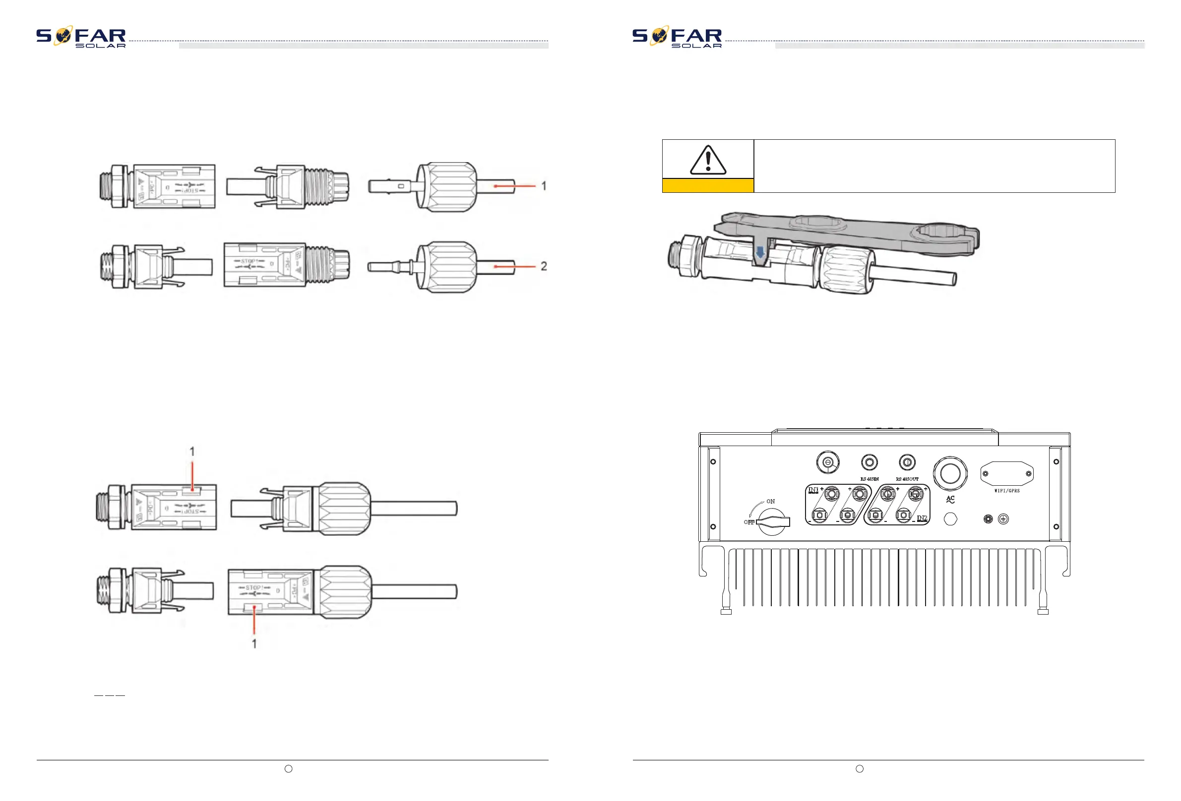
Step 3 Insert the positive and negative power cables into corresponding cable glands.
Step 5 Insert crimped power cables into corresponding housings until you hear a "click" sound.
The power cables snap into place.
End
Figure 4-26 Connecting DC input power cables
Step 4 Insert the stripped positive and negative power cables into the positive and negative
metal terminals respectively and crimp them using a clamping tool. Ensure that the cables
arecrimped until they cannot be pulled out by force less than 400 N, as shown in Figure 4-27.
1. Positive power cable 2. Negative power cable
Step 6 Reinstall cable glands on positive and negative connectors and rotate them against the
insulation covers.
Step 7 Insert the positive and negative connectors into corresponding DC input terminals of
the SOFAR 10-20KTL until you hear a "click" sound, as shown in Figure 4-28.
Figure 4-27 Connecting DC input power cables
1. Bayonet
Follow-up Procedure
To remove the positive and negative connectors from the SOFAR 10-20KTL, insert a removal
wrench into the bayonet and press the wrench with an appropriate strength, as shown in
Figure 4-29.
Figure 4-28 Removing a DC input connector
Caution
Before removing the positive and negative connectors, ensure that the DC
SWITCH is OFF.
SOFAR 10K~20KTL
User manual
SOFAR 10K~20KTL
User manual
4.6 DRMs Functions
4.6.1 10-20KTL have five TTL input and one 5V Power output witch provided the DRMs
function. The Ports are RG/0,CL/0, DRM1/5, DRM2/6, DRM3/7, DRM4/8, and GND ,5V,as
shown below :
4.6.2 PINs Physical Function Discription:
The DRMs function allocation is shown in below Table: