Technical Manual 9200
REF: 380/5 8
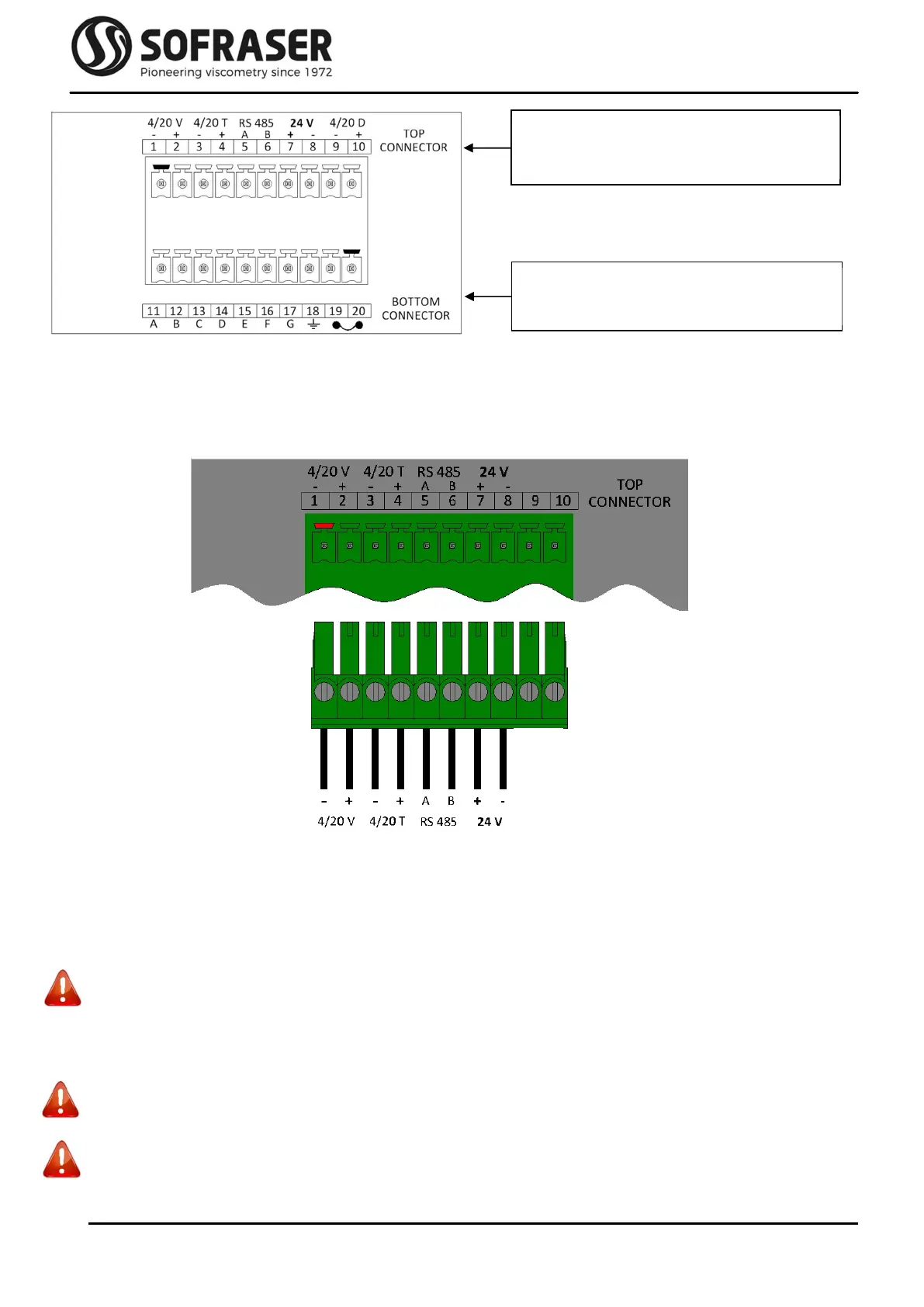
2.3.1
Top connector
Connections for the top connector (not cabled in our picture example) have to be made by the user
scrupulously respecting the following indications.
The plugging scheme of the top connector is as follows:
Pins 1 to 4 are 4/20 mA outputs for Viscosity and Temperature. They have been calibrated according
to customer's request. They must be connected to installations with an impedance of not more
than 350. It is recommended to use armed cables for these outputs and the shield should be
pressed in the earth terminal screw. They are already powered internally.
When the measured value is out of the configured range of the 4/20 output (below minimum value
or over maximum value), the output passes in default mode and is forced to 22 mA.
Never connect the 4/20 mA outputs to a power supply, an active PLC input or tester
Pins 5 and 6 are used to connect the RS-485 cable in order to communicate with an external
console.
Pins 7 and 8 are for the 24 VDC (± 2.4 V) stabilized and filtered power supply.
Caution: watch out the polarity
Pins 9 and 10 are not used.
Caution: Do not plug anything.
Interface to the outside world
(Outputs and power supply)
Links to the MIVI sensor and earth
grounding