Technical Manual 9200
REF: 380/5 9
*
2.3.2
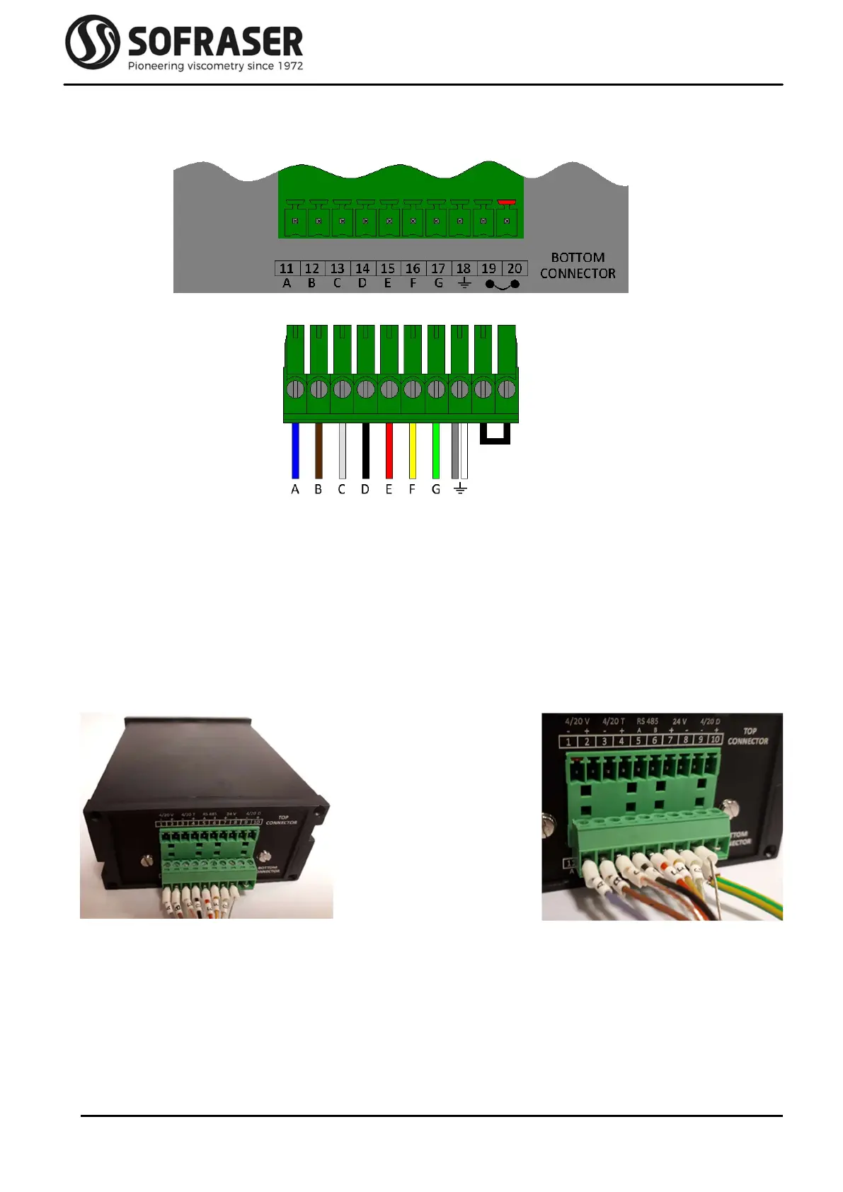
Bottom connector
The plugging scheme of the bottom connector is as follows:
Pins 11 to 14 make the connection between the electronic board and the MIVI sensor itself. This is
how the driving signal is generated and how the receiving signal is measured.
Pins 15 to 17 are used to connect the Pt100 probe wires.
Pin 18 is the Earth connection.
* The white wire of the MIVI is only present for intrinsically safe version of the sensor. For other
configurations, this white wire is cut and only the metal wire is connected to Pin 18.
Pins 19 and 20 are not used. By default, a wire makes the shortcut between the two pins (see picture
2).
Picture 2.1: bottom connector
When the cable is short and the
sensor is correctly earth grounded
Picture 2.2: bottom connector
It may be necessary to earth ground the
transmitter directly on PIN18