MIVI Technical Manual
REF: 379/4 12
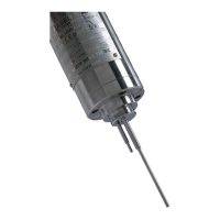
2.2.1
Various mountings and models
Details about mounting accessories are available in technical leaflets reference 320, 328 and 329
(see APPENDIX D). When it normal production cycle, the vibrating rod must be continuously
and fully immersed in the fluid.
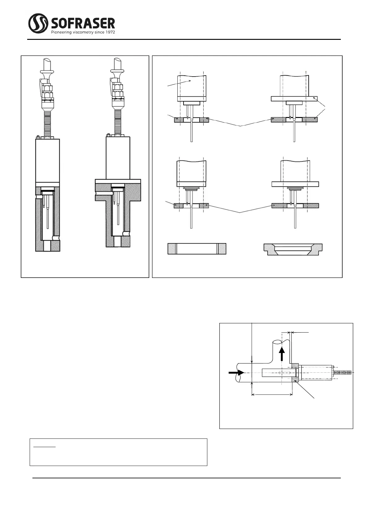
2.2.2
Elbow mounting
The flange is welded on a right angle straight tee as indi-
cated in figure 1.
The minimal pipe diameter is of 32 mm.
The length of the branch must be reduced as much as pos-
sible.
The flange and the pipe axes have to be superimposed.
The flow direction is as indicated on figure 1 (unless for fi-
brous fluids where the flow is inverted and the flow
damper removed).
A free area of at least 150 mm length is necessary.
Advice: Choose a sensor position in order to assure a
permanent fluid renewal and to avoid the
existence of “dead zones”.
5 mm max.
150 mm min.
Mounting flange,
welded
high pressure
standard
replacement ring
sanitary
replacement ring
high pressure
Ex-proof MIVI
on a ¼ gas pot
Ex-proof MIVI
on a ¼ gas pot
mounting flange
sanitary standard pressure
mounting flange
standard pressure
Ø 60
Ø 76
Ø 99
or
114
sanitary design
standard design