Do you have a question about the Sofraser MIVI and is the answer not in the manual?
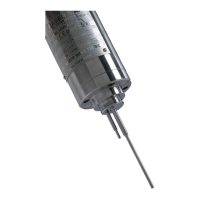
The MIVI is a process tuning rod probe designed for viscosity, density, and temperature measurements. It is a robust and versatile instrument used in various industrial applications, including food and beverage, pharmaceuticals, biotechnology, and cosmetics.
The MIVI sensor is composed of two inseparable elements: the sensor and the electronics device that controls it (also called transducer). The sensor cannot be used with another electronic device because they are matched together as one vibrating system. The device operates on the principle of a vibrating rod held in oscillation at resonance frequency by a driving magnet. The amplitude of the vibration is damped by the viscosity of the fluid. The sensor receives a coil that detects the response and the signal is converted to a viscosity value through the electronics device. The factory calibration is performed with certified viscosity standards. The transducer acquires the coils' voltages and generates various signals. These signals represent the properties being measured, and the transducer is also in charge of powering the whole system. The MIVI sensor is capable of measuring viscosity, density, and temperature simultaneously.
The MIVI sensor is available in various models, including general standard, sanitary, Ex-proof (ATEX, FM, JIS, KOSHA), high-pressure (up to 1000 bar), and special models (according to the requirements of material and design). The standard temperature probe is a Pt100 class B.
Cable Wires Allocation:
European Pressure Equipment Directive and EMC Directive: The MIVI sensor complies with article 4.3 of the PED 2014/68/UE for higher pressure sensors. The mounting flange is an accessory to be welded on the process line.
ATEX and IECEx Flameproof Enclosure Certification: The MIVI sensor is certified for use in hazardous areas. Marking includes:
FM Flameproof Enclosure Certification: MIVI FM sensors are approved for equipment installed in explosive gas atmospheres.
ATEX and IECEx Intrinsic Safety Certification: Marking includes:
Japanese Ex approval (JIS) and Korean Ex approval (KOSHA) are also available.
Sensor Installation:
Elbow Mounting: The flange is welded on a right angle straight tee as indicated in figure 1. The minimal pipe diameter is 32 mm. The length of the branch must be reduced as much as possible. The flange and the pipe axes have to be superimposed.
Plane Side Mounting: The flange is welded on a metal plate as indicated in figure 2. The free area around the vibrating rod has to be at least Ø 40 and 150 mm length. In order to avoid parasitic vibrations, the plate where the flange is welded must be thicker than 5 mm.
Mounting on Flow Cell, for Small Flow Rates or Pilot Plant: The small size of the sensing element allows many different mounting features according to the user's requirements. See example on figure 3 for the mounting cell (chamber/pot).
Replacement Cap and Ring: For standard pressure models, most of the mounting accessory sets delivered by Sofraser are provided with an obturator kit (cap, O-ring, 4 fixing screws CHC M6) that allows the process to work when the sensor has to be removed.
Flow Damper: Each sensor is equipped with a flow damper (tube) in order to stabilize the flow around the vibrating rod. The fluid renewal is done through the slits of the damper. It is advised to keep it on the sensor unless the sensor is used in particular conditions (on flow cell mounting, sanitary use, very viscous fluids). At the time of the assembly on the mounting flange and during transport, it also protects the rod from mishandling. Before installing the MIVI sensor on its mounting accessory, check that the flow damper is firmly screwed on the neck of the MIVI sensor.
Tightness: The tightness between the MIVI sensor and its mounting accessory is assured by one O-ring (three for the sanitary model). Check that the O-ring(s) material is compatible with your fluid and the operating temperature. The flow damper of MIVI with base design (left drawing) is screwed on the neck of the vibrating rod flange. But removing the flow damper of MIVI with sanitary design requires to unscrew the 3 M3 STHC screws (right drawing) in order to release it from the neck of the vibrating rod flange.
Fluid Homogeneity: The MIVI is fully compatible with biphasic fluids, gas emulsions and solid suspensions. There is no impact with particles size up to 1 mm. Larger particles could disturb the measurement and/or damage the sensor.
Chemical Compatibility: The MOC of the wetted parts of the standard MIVI sensor is 316L stainless steel. In option, PTFE, ADLC and enamel coatings as well as special alloys and electropolish finishing are available. The sheath of the standard cable of the MIVI sensor is in PVC material and its cable gland is in chrome-plated brass.
Temperature Compatibility: The maximum temperature of your process is within the nominal temperature of your MIVI sensor. For information, standard MIVI sensor has a 200 °C (392 °F) nominal temperature. In option 250 °C, 300 °C, 482 °C or 572 °C are available. MIVI sensors with incorporated Pt100 temperature probe must not be used above 250 °C. The temperature of the cable and especially at the output of the cable gland must not exceed the temperature written on the marking plate (100 °C (212 °F) by default).
Pressure Compatibility: During normal operation, do not exceed the MIVI sensor rated pressure.
Sensor Handling: Do not drop or knock the MIVI sensor. Knocking the rod will have an effect on the factory calibration. It can be corrected on site. Bending may block the vibration of the rod and require factory maintenance. In case it is necessary to work without the flow damper, the mounting of the MIVI sensor must be made with precaution, in order to avoid knocking or bending the vibrating rod. The minimal bending radius at the flexible pipe (electric outlet) is 100 mm. A shorter radius can crush the turns, initiate cracks, generate leakage inside of the MIVI, then failure.
Mounting Screws Torque: Torque at the mounting screws: 9 N.m ± 1 at the M6x100 screws (4), or 21 N.m ± 1 at the M8 screws (8 for the high pressure design), or 42 N.m ± 1 at the M10 screws (8 for the very high pressure design).
Grounding and Wiring: The MIVI sensor and the electronic devices must be connected to a good earth ground at the same voltage level. Use the screw dedicated to the grounding that is implemented on the MIVI sensor.
Checking the Equipment When Placed in the Process Line: Before starting the process, check that the viscosity information is stable (vibrating rod in the air). If not, check first the strength of the sensor fitting. Otherwise rotate the sensor of 90° (4 possible positions). Choose the position where the information is the most stable. Locate this position in order to restore it when the sensor is removed and reinstalled. Adjust the mounting offset, at room temperature. The rod is vibrating in the air.
Offset Adjustment in Air: The offset of the raw signal must be performed before utilization and introducing fluid in the process. This is a mandatory step to ensure the reliability of the measure. The clean and dry rod must vibrate in the air since at least half an hour before the offset adjustment is carried out, in order to warrant the homogeneity and the stability of the MIVI temperature on its mounting accessory (best at ambient temperature). Refer to the manual of the electronics for the detailed instructions. The amplitude, corrected with an offset, is shifted so that the viscosity value is 0.00 cP. When offset is confirmed, write it down as well as the raw values (see electronics manual) in the follow up file of your instrument.
Reference Point: When possible, note the viscosity information and raw values when a cleaning or rinsing solution is flowing. Beside of the condition "in the air", this can be used as reference for some periodic controls of the equipment. The operation must be done each time in the same conditions (rod in the air, or in the cleaning solution). Such a control can be assimilated to a self-checking. If the original calibration has been modified, the reference values will of course be those obtained with the new calibration.
MIVI Utilization: Be sure that the offset in the air has been performed before introducing the fluid in the process. Refer to the electronics manual for display, advanced data processing and output features.
Periodic Checking: Conformity to regulations relative to Quality Insurance implicates a periodic control of the measuring equipment used in the manufacturing operations, taking in consideration (or correcting) their drift in time. It is proven that this equipment drift is negligible. However, it is good to check their aspect and their response once a year, at the same time as the other process equipment. A quick control is possible from time to time. If the sensor active part is in air, or immersed in a cleaning or rinsing solution. As long as these values stay similar, we can say that the sensor operation is right among its whole range (if no intermediate re-programming occurred).
Modification of the Previous Calibration: The paired transducer has been programmed in order to perfectly answer to the customer's needs. These settings are noted in the factory "specific notes and manufacturing parameters" pages that are delivered with the documentation. The factory calibration is performed with certified viscosity standards (Newtonian mineral oils). In normal conditions, there is almost no drift of the calibration. Nevertheless, the need for calibration update isn't abnormal. At first, be sure that the modification is necessary, and not consecutive of a non-coherent comparative information (different measuring conditions, bad standards, inaccurate or wrong laboratory measurements...). The initial calibration parameters are protected and can only be modified at SOFRASER. For any modification, check in the electronic manual if this operation is allowed or contact your distributor. Calibration update at SOFRASER workshop is the first solution. Please contact your distributor or SOFRASER after sales team.
Periodic Maintenance: MIVI sensor has no moving parts and can be operated without maintenance in some specific conditions. Nevertheless, SOFRASER advises to check the MIVI sensor once a year. Each end user can reduce or increase this period of time according to his policy and specific operation conditions. The check can be done by end user, SOFRASER distributor or SOFRASER after sales workshop. SOFRASER advises to proceed to hereunder check:
| Check | Expected The following is a description of a device based on the provided manual pages.
The MIVI is a process tuning rod probe designed for measuring viscosity, density, and temperature. It is a robust and versatile instrument suitable for various industrial applications, including food and beverage, pharmaceuticals, biotechnology, and cosmetics.
The MIVI sensor system comprises two inseparable elements: the sensor and the electronics device (transducer). These components are factory-matched and function as a single vibrating system. The sensor operates on the principle of a vibrating rod, which is kept in oscillation at its resonance frequency by a driving magnet. When the rod is immersed in a fluid, the amplitude of its vibration is damped, and this damping is directly related to the fluid's viscosity. The sensor incorporates a coil that detects the rod's response, and the signal is then processed by the electronics device to calculate the viscosity value. The factory calibration of each MIVI unit is performed using certified viscosity standards.
Beyond viscosity, the transducer also acquires voltage signals from the coils to provide measurements for density and temperature. The electronics device is responsible for processing these signals and powering the entire system, making the MIVI a comprehensive tool for simultaneous multi-parameter fluid analysis.
Models and Configurations: The MIVI sensor is available in several models to suit diverse industrial requirements:
Temperature Measurement: A Pt100 class B temperature probe is integrated into the sensor for accurate temperature readings.
Cable Wires Allocation: The wiring configuration for the MIVI sensor is as follows:
Regulatory Compliance:
Hazardous Area Certifications: The MIVI sensor holds multiple certifications for safe operation in hazardous environments:
Materials and Construction:
Operating Conditions:
Installation Flexibility: The MIVI sensor can be installed in any orientation, including upside down. However, for optimal performance, horizontal installation or with the cable gland oriented downwards is recommended. The mounting flange, typically supplied with screws (M6x100, M8, or M10 depending on pressure rating), is designed to be welded onto the process line.
Mounting Options:
Flow Damper: Each MIVI sensor includes a flow damper (tube) to stabilize fluid flow around the vibrating rod and protect the rod during transport and assembly. It is generally recommended to keep the flow damper installed unless specific process conditions (e.g., very viscous fluids, sanitary applications) require its removal.
Tightness: An O-ring (or three for sanitary models) ensures tightness between the sensor and its mounting accessory. Compatibility of the O-ring material with the fluid and operating temperature must be verified.
Pre-Operation Checks: Before initiating the process, it is crucial to verify the stability of the viscosity reading in the air. If unstable, check the sensor fitting and rotate the sensor by 90° increments to find the most stable position. This position should be noted for future reinstallation.
Offset Adjustment: A mandatory offset adjustment in the air must be performed before introducing fluid into the process to ensure measurement reliability. The clean and dry rod should vibrate in the air for at least 30 minutes to stabilize the MIVI temperature on its mounting accessory. The amplitude, corrected with the offset, is set to yield a viscosity value of 0.00 cP. The offset values should be recorded.
Reference Point: It is advisable to establish a reference point by noting viscosity information and raw values when a cleaning or rinsing solution is flowing. This serves as a self-checking mechanism for periodic controls, ensuring consistency and detecting any calibration drift.
Periodic Maintenance: The MIVI sensor, lacking moving parts, generally requires minimal maintenance. However, SOFRASER recommends an annual check, though the frequency can be adjusted based on operational conditions and company policy. These checks can be performed by the end-user, a SOFRASER distributor, or a SOFRASER after-sales workshop.
Recommended Checks:
Troubleshooting: The manual provides a troubleshooting guide for common issues, including:
Return Instructions: For any returns, contact your distributor or SOFRASER for a Return Materials Authorization form and complete decontamination statement.
End of Life: The MIVI sensor is designed for 24/7 utilization and has a lifespan of years or even decades. At the end of its life, the MIVI sensor can be dismantled and recycled. SOFRASER advises returning the equipment to its workshop for proper dismantling and recycling of components.
| Brand | Sofraser |
|---|---|
| Model | MIVI |
| Category | Measuring Instruments |
| Language | English |