MIVI Technical Manual
REF: 379/4 13
2.2.3
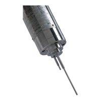
Plane side mounting
The flange is welded on a metal plate as indicated on fig-
ure 2.
The free area around the vibrating rod has to be at least
40 and 150 mm length.
In order to avoid parasitic vibrations, the plate where the
flange is welded must be thicker than 5 mm.
Advice: Preferably choose a horizontal position for the rod
placement with all the liquid flows turned to the
top in order to avoid the apparition of bubbles.
2.2.4
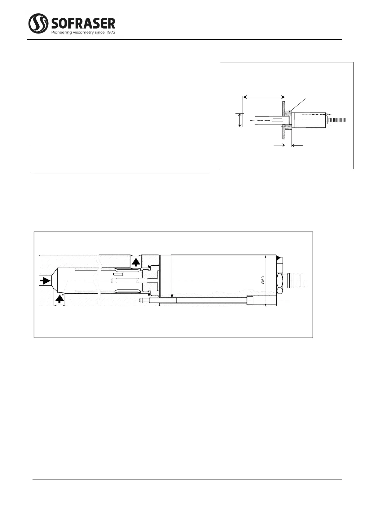
Mounting on flow cell, for small flow rates or pilot plant
The small size of the sensing element allows many different mounting features according to the
user's requirements. See example on figure 3 for the mounting cell (chamber/pot).
2.2.5
Replacement cap and ring
For the standard pressure models, most of the mounting accessory sets delivered by Sofraser are
provided with an obturator kit (cap, O-ring, 4 fixing screws CHC M6) that allows the process
to work when the sensor has to be removed.
For some applications and operating conditions it may be advised to install the MIVI without its
flow damper. In this case the flow damper must be replaced by the replacement ring that is
delivered with most of the mounting flanges.
2.2.6
Other mountings
Other mountings are possible; refer to technical procedure reference 319 (see APPENDIX D).
figure 3
17 mm
welded